Continue to Site

Eng-Tips is the largest engineering community on the Internet

Intelligent Work Forums for Engineering Professionals

  • Congratulations GregLocock on being selected by the Eng-Tips community for having the most helpful posts in the forums last week. Way to Go!

Calculations for checking design of Lifeline Anchor

Status
Not open for further replies.

sean09

Mechanical
May 3, 2009
16
Hi guys,

I am trying to work out how I could do the calculations on a design for the attached lifeline anchor.

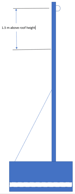
The attached sketch shows the concept made of 50x50 SHS inserted into 60x60 SHS which is encased in concrete.

The idea is to set one of these at either end of a cabin, attach a safety line onto each end which in turn would allow harnesses to be attached to it. This would let a couple of guys walk along a roof of a cabin.

They need to be able to support two grown men (total 190kgs) and a lifeline.

I want to be able to show if the 50x50 is sufficient or not, and if not then suggest an alternative.

I'm lost as to how to approach this and would appreciate any help.
 
 https://files.engineering.com/getfile.aspx?folder=38da3c7e-635f-4497-92fa-7d2f55e82f12&file=Untitled_09122021_120900.pdf
Replies continue below

Recommended for you

This thread may be helpful -
You appear to have a fairly flexible support - this will impact how you determine the tension/geometry of the loaded cable and will add to your loaded sag. If you don't have much distance to fall, the loaded sag of the cable could create a safety hazard (i.e. users make contact with ground below before system is fully engaged).

Is this being used as fall arrest or travel restraint? This will make a big difference in your design as well.
 
I'll comeback with some further specifics. But a couple general statements:
There is a good book on fall protection "Introduction to Fall Protection" by Ellis. Kinda expensive, but if you do a fair amount of it, it might be worth it.
In the USA, OSHA is typically the referenced standard for fall protection. They provide loading criteria.
Also a good article here: LINK about horizonal life lines (little different than your case)


I've used this in the past. I spent a few hours validating it (it provides all of the calculations on the report). I recall it working pretty well for determining life line anchor loads.
 
I'm wondering if this is a fall arrest anchor (the workers can reach, and fall over the edge) or a travel restraint system (the line keeps the workers from reaching the edge).

My gut would say this could work in a travel restraint system.

However if this is a horizontal lifeline (HLL) fall arrest anchor, there will be huge forces at these anchorages. Between bending of the HSS and tipping/sliding of the base my guts says this isn't an adequate anchor. Some bending / tipping may allow the system to work, but at the cost of greatly increasing the clearance needed. There are commercial anchors that use tipping as part of their intended arresting method. Only the calcs could say for sure.

The link from phamEng very looks interesting. IRSST would seem to be an excellent place to trust but if the system fails saying "I got the loads from some internet site" won't be much good. Nonetheless, I expect I will be visiting the IRSST site again to read some of their research and back ground info.

Of the various fall arrest systems, HLL's are by far the most difficult to design properly. I would recommend finding someone trained in HLL design if that's what you need.
 
Geoff14- I'd say it depends on the configuration of the roof, but for "a cabin" I'd bet it's a fall arrest. Travel restraint keeps you approaching the hazard. On a sloped roof, a misstep and you're already falling, albeit not quite in free fall. I'd only use travel restraint if the roof is flat and it keeps you in areas where falling is akin to tripping at grade.

Life lines are a good place to be conservative.
 
My thoughts.....

1. Depending on your location, OSHA requirements may or may not apply

2. Not sure what the brace is for. The fall restraint load could occur in any direction. Wouldn't you need to brace other directions?

3. Each block of concrete would weigh about 4k. Not sure what sort of "cabin" construction you have, but can it support these loads in addition to 5k per guy attached?

4. If you are running a safety line/cable between each block for harnesses to hook onto, there would need to be quite a bit of tension in that cable to support the load imposed by 2 guys falling from a roof. Maybe I am not understanding the arrangement.
 
I have developed a spreadsheet for analyzing the forces and deflections in a horizontal lifeline.[ ] It can be downloaded from my website (
However it assumes the lifeline cable has rigid end supports.[ ] My first thoughts on how to allow for non-rigid supports are either to use the spreadsheet iteratively or to "adjust" the cable's extensibility to include the effect of the flex in the supports.[ ] The latter approach would require an assumption that the support points deflect linearly.
 
Oh dear god! [surprise]

When it finally dawned on me what exactly you were trying to do with this, how high it is, and how you were trying to achieve this I had to scratch out my entire post. This is a TERRIBLE idea and is grossly under designed for the required purpose.

This thing will overturn readily with just static load, let alone dynamic load. You would need block about an order of magnitude bigger to resist even static forces. In fact if you want a horizontal line of any reasonable length this will overturn without ANY added load from a lifeline.

Either let somebody who knows what they are doing design this or go right back to basics and start drawing load paths and static diagrams with a horizontal line. Because it seems you have completely skipped this step.


sean09 said:
I'm lost as to how to approach this and would appreciate any help.

-Check strength against maximum required load. (Typically 20-25kn under most codes)
-Check over turning against maximum required load
-Check shear against maximum required load
-Check whether your code requires 2x(25kN) for an anchor that has two people. (This is a totally improbably event, but codes may require it.)
 
Hmm...good point human909. I didn't try to convert the metric measurements and it didn't dawn on me how incredibly small that thing is either. Footing overturning and tube yielding would probably happen simultaneously...as it gets put up.
 
I should mention that I've never designed to code horizontal lifeline system and don't know what various codes require. But I should point out that while the forces of line tension of a static load are significantly magnified compare say a single anchor point. The magnification of dynamic loads on a horizontal line are significantly reduced compare to a dynamic load on a single anchor point. Essentially the load magnification factor 1/sin(theta) reduces significantly as the load increases thus is a natural limiting factor on the peak forces.

This can be readily seen in the following demonstrations:

Though in the videos above 3.5-5kN were the peak loads because more stretchy lines were used. With are typical wire rope cable [highlight #FCE94F]you can expect loads in excess of 10kN[/highlight] even on a static load and 15kN on a dynamic load.

Note these are TYPICAL loads of one person. They are not design loads!

EDIT:
I cannot emphasis enough that you should let somebody who knows what they are doing design this. Other people here have given you just enough rope to hang yourself. You have an initial design that is grossly under specified. This sounds like a backyard 'engineering' job and something your should not be doing when other peoples lives are clearly at stake.
 
Thanks, everyone for your replies and advice.

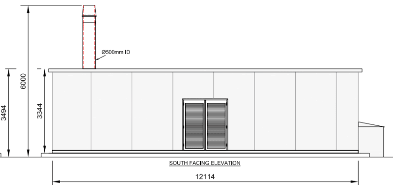
I work for a company that designs and produces pre-fabricated plant rooms. So this is what I mean by a cabin. The lifeline anchor is something the fabrication shop has sent up for calculations and design to be done.

A typical example of a cabin is below.
Cabin_kyygj0.png


Another image of the concept is seen below

Lifeline_Anchor_i5nzym.png


Motorcity, yes there should be more bracing around the base. This just wasn't sketched in

There's a lot of good info which has been given for me to go through, but human909 I have to agree with you. I'm not a structural engineer and my gut feeling when this came to me was "this needs to go out to a structural engineer to access, or purchase from fall prevention specialists".

I wanted to put the post up though so I could get a few opinions from experts like yourselves and a better understanding of all that is involved.
 
Status
Not open for further replies.

Part and Inventory Search

Sponsor