Eng-Tips is the largest engineering community on the Internet

Intelligent Work Forums for Engineering Professionals

  • Congratulations waross on being selected by the Tek-Tips community for having the most helpful posts in the forums last week. Way to Go!

Calibration of EEG device 2

Status
Not open for further replies.

advertiser

Bioengineer
Jun 25, 2015
2
0
0
VN
Hi everyone,
I have just made an EEG recording device.
Now I need a calibration system which can generate sine/square wave of 50uV amplitude.
As far as I research on the market, there is no Signal generator can generate under 1mV for a <$1000 price.
Some one suggest me to connect [Signal Generator (1)] -> [-60dB Attenuator(2)] -> [EEG device] but I am not sure it is correct or not.
Could anyone please suggest me some products for (1)+(2) or a more cost effective solution? My budget is <$2000.
Best,
 
Replies continue below

Recommended for you

Using a calibrated attenuator it is trivially easy to create a signal of any arbitrary amplitude below the normal range of your signal generator. You can normally select an output amplitude range and an available attenuator, and tweaking the normal continuous output amplitude adjustment, to get whatever amplitude you want.

If you have an external measuring device (meter), then it's standard practice to measure the higher amplitude before the attenuator (which is easy) and then simply trust the nameplate dB value on the attenuator. Commercial applications use Calibration certificates to provide a foundation for the trust.

Other topics to consider:

The dB value will be a Power ratio. It takes a bit of trivial math to work out the resultant voltage.

Many attenuators will be designed for 50-ohm system impedance, and their actual attenuation would only be accurate if the load is 50 ohms. If your load is not 50 ohms, then you'll have to do some mathematics to calculate the applied voltage. Or, if the load is higher, then you could apply a parallel load resistor of a calculated value to make a new load of 50 ohms.

Non-resistive loads can get complicated.

Noise. Your EEG display will make this visible, so should be easy to monitor.

 
Thanks VE1BLL!

I will try the voltage divider first because it is cheaper than an attenuator. The results will be updated for discussion.

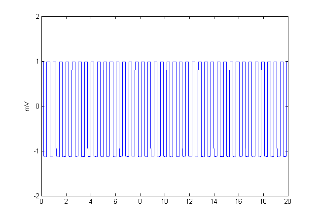
Here is my test with 1mV input square-wave.

sqr_test_jeczha.png
 
What's the frequency range? If it's for an EEG, then I assume it's fairly low (audio) frequency range (based on how slowly most people think, LOL).

Here's another trick. Instead of making one attenuator, and then lacking the instrumentation to calibrate it (because the output is too low), divide it into two or three equal attenuators. Then each can be individually calibrated and then used in series.

Watch out for the other points already mentioned. Especially load impedance.


My thoughts are:

[ol 1]
[li]The human body is not calibrated and electrode placement is hit and miss, so highly accurate calibration is not required. All you need is a sanity check and maybe a feel-good demo (perfectly valid objectives!)[/li]
[li]Taking "attenuator" to mean voltage divider with impedance matching, that's a waste of effort. Two resistors as a simple voltage divide will be fine. The input impedance of an EEG amplifier is super high, so the impedance of the voltage divider is irrelevant. If you have a 1V signal, 1K and 20K will do the trick.[/li]
[li]Much more important is the common mode rejection of your amplifier. How much output signal does it produce when all inputs are tied together and you hold the input wire?[/li]
[/ol]

David Stonier-Gibson


Oops: Should have been 1 Ohm and 20K. Better still 100Ohm and 2MOhm, so wire resistances are eliminated.
 

Almost 50 years ago, my first job was at Kaisers Lab. A company that made some of the first EEG machines. Actually his first amplifier with transistors instead of tubes, was so good that it was used by NASA for the first manned space flight. The voltage divider for the test generator was made by Kaiser himself. A simple switch that switched in different resistors made of Constantan wire. Connecting it to a generator with a known voltage output, the switch could select 10uV, 25uV, 50uV and more voltages that I can't remember.
It is easy and cheap to make. The most expensive is a good rotary switch.
With the high input impedance of the EEG amplifier, you don't have to worry about loading the voltage divider.
The voltage divider is easy to make with the known resistance per length of Constantan wire. For SWG20 wire the resistance is 0.7445Ohm/meter that means that 134.5cm of wire have a resistance of 1 Ohm.
If you use that length of wire connected through a 10K resistor to a 1V voltage source, you will have 10uV for each 10 cm of the wire. If you make the first connection with your switch after 13.45 cm you will have 10uV here, the next connection after 33.57cm will give you 25uV, after 67.15cm you have your 50uV and on the top of your wire you have 100uV. The common terminal on the switch is the output to your EEG amplifier.
If you connect your voltage divider to a higher voltage, it is easier to measure the output voltages with an oscilloscope, to see that it works.


Status
Not open for further replies.
Back
Top