Eng-Tips is the largest engineering community on the Internet

Intelligent Work Forums for Engineering Professionals

  • Congratulations waross on being selected by the Tek-Tips community for having the most helpful posts in the forums last week. Way to Go!

Can a cause and effect diagram be used in the design of complex machinery?

Status
Not open for further replies.

EngKen

Electrical
Feb 25, 2015
3
0
0
BE
I understand cause and effect diagrams can be used as input to write software for simple applications. What about more complex applications/machinery? What to use than? A control narrative/philosopy?
 
Replies continue below

Recommended for you

Howdy Ken,
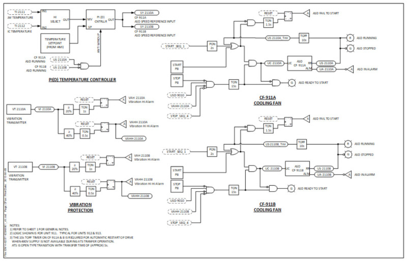
I routinely use a Boolean-style logic diagram for more complex logic. Yes, it does take time to develop, but I have yet to find better way to transfer my thoughts to the programmer.
GG
2017-12-08_17-00-20_v4ob66.jpg


"I have not failed. I've just found 10,000 ways that won't work." Thomas Alva Edison (1847-1931)
 
Hi GG,

I like that style of presentation too. I first met it when I started working on Westinghouse turbines and generators. Somewhere I have a fairly full Autocad library of digital logic symbols, analogue blocks, etc. if that's of any interest?
 
i used that format when i was doing work for P&G projects. I must of made like 10000 of these diagrams on 1 project, painful memory. I think they were called Boolean logic diagrams. All the most complex function blocks was basically what the plc manufacturer put out as a block diagram.

 
Cause and effect diagrams are unlikely to adequately capture nuances of timing, multiple events, and conditional events.

Logic diagrams can be translated into something like VHDL, which would be roughly equivalent to pseudo-code. If the diagrams are done in a suitable CAD program, VDHL essentially comes automatically.

TTFN (ta ta for now)
I can do absolutely anything. I'm an expert! faq731-376 forum1529 Entire Forum list
 
Status
Not open for further replies.
Back
Top