Continue to Site

Eng-Tips is the largest engineering community on the Internet

Intelligent Work Forums for Engineering Professionals

  • Congratulations waross on being selected by the Eng-Tips community for having the most helpful posts in the forums last week. Way to Go!

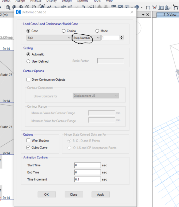
Can someone explain what is step number 1 2 3 ? and why does displacement in step 1 2 3 differ ? 1

Status
Not open for further replies.

curiousinvite

Civil/Environmental
Apr 24, 2021
42
Capture_prjpgo.png
 
Replies continue below

Recommended for you

Usually those steps relate to added eccentricity in seismic cases. If you open your load patterns, I would assume you have X load, X +e, X-e, where the e is your code required eccentricity.

That would explain why displacements may differ as well.

S&T -
 
Correct, it relates to the eccentricities in the defined static earthquake load cases, if you view the base reactions, you should see that the Fx, Fy, Fz, Mx & My are all the same, Mz varies with eccentricity. If you have set 0.1 for the eccentricity and checked positive, central and negative eccentricty, the 3 load steps relate to each of these eccentricities.
 
thanks for the reply , one more question why does Mz varies if the eccentricities are in x and y axis ?
Also shouldn't the moment value for X load should be lower than X +e, X-e ?
Capture_umf7zf.png
 
No, My is the moment about the global y-axis caused by Fx. Likewise Mx is the moment about the global X axis driven by Fy. These moments don't change cause Fx & Fy get applied at the same z-offset from the base of the structure. Mz is the twist about the global Z-axis by the Fx & Fy being applied at different x & y positions on the building
 
Status
Not open for further replies.

Part and Inventory Search

Sponsor