Eng-Tips is the largest engineering community on the Internet

Intelligent Work Forums for Engineering Professionals

Can someone explain why only one insulated power cable overheated in a paralleled bundle?

Status
Not open for further replies.

bdn2004

Electrical
Jan 27, 2007
792
0
0
US
At this plant site they replaced an oil filled transformer with a similar existing oil filled transformer 17/27MVA OAFA, 15kV-575V transformer.
It typically runs on the secondary side at 20,000 Amps per phase.

The new transformer had been previously connected by bus work between the transformer secondary bushings and the load, a rectifier. One bus per phase.
There are short pieces of braided copper between the two connections.

It's new location however required cabling instead of bus to be installed between the secondary bushings and it's load, a different rectifier.
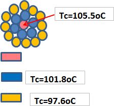
The design called for DLO777 type cable because of the tight area and flexibility required. Ampacity 900Amps per phase if used in free air. So they used like 24 of these cables per phase.
When they did an infrared scan on the installation - one of the cables in the bundles had overheated - like up to 300 deg F. And then it spread over time to the other cables.

Why would only one cable do that ?


Replies continue below

Recommended for you

Bundles and "in free air" are not compatible. 72 cables, in free air, is going to take a huge amount of space. Then the need to be scrupulously kept to as near the same length as possible. So if the middle of the bundle turns out the be the physically shortest cable it's the one that going to run the hottest for many reasons.
 
Thanks, that makes sense. I guess the definition of "free air" needs to be more defined. All of these cables are like 25' long. For the majority of that run it's not in a bundle like that - but up at and near the termination it is - and that's where the hot spot is.

I know in the NEC with cables that are in conduit and then cable tray...if the conduit is 6' or more - it's the tables for conduit that have to be used. Maybe that's what the designers were thinking.
 
Heat originating at the termination sometimes means a bad crimp or loose bolt. Are the terminations listed to operate at 90 deg C? Terminations with a 75 deg C listing would have a limit of less than 800 A per conductor. This might just be the first overloaded termination to start thermal runaway.

Having seventy-two 777 kcmil cables terminating in one location is a large amount heat to dissipate. I am having trouble picturing how the cables could possibly be sufficiently spaced to assume free air.
 
It is an example of 19 single core cables of 240 mm^2 [500 MCM] copper conductor 0.6/1 kV XLPE insulated in free air of 40oC.
If the current flowing through all cables is 320 A then red conductor temperature will be 90oC.
If the current will be 380 A the center is 105.5 oC the blues are 101.8 and the yellow 97.6 oC.

19_PARALLEL_CABLES_HEATING_d4rgup.jpg
 
I'm with Bacon on this.
One bad connection will develop heat.
In some installations that heat will eventually compromise other connections.
Re Free Air. That requires a specific spacing between conductors, and free air movement.
That is in open air, not in an overall enclosure.
Here is one definition of "Free Air"
in a free air run, with a
cable spacing not less than 100% of the larger cable diameter, as specified in Table 1;
There is an allowance for closer spacing without de-rating for lengths of 600 mm or less. That allows for connections.
Copper is very good at conducting the heat away from the closer spacing.

Bill
--------------------
"Why not the best?"
Jimmy Carter
 
575 volts / 20 kA sounds like a melting furnace. I never worked on one using a rectifier, but all of the issues are the same with AC furnaces.

Factory furnace leads now are usually water cooled. This is an option if your rectifier and / or transformer already have water cooling. Likely if this is a melting furnace application. Southwire is one of the sources
Old style was open bare copper loose bundles, our application used 6 bare cables at 20,000 A per phase with each phase strung through wooden doughnuts spaced about 3 feet apart. Reason for the doughnuts was to make sure the magnetic forces could not make the cable bundles touch each other. At the terminations the lugs were always well spaced.

I agree with all of the comments above about the difficulty of ensuring the cables pass the same current, and the difficulty of cooling this many cables closely packed near the terminations, and possibly the entire run
 
DLRO cables have fine strands to make them flexible, but it also makes them difficult to terminate reliably in large sizes. The strands don't compress well, leading to loose joints.

It doesn't take much of difference in impedance for a single conductor to carry a lot more than its share of the current. On just 6 conductors per phase I've seen current variations of 25% or more between cables on the same phase. (6- 500 kcmil/phase, each group triplexed in tray). If you are feeding a rectifier, there are a lot of higher harmonics which would also generate higher impedance and make the current division worse.
 
Status
Not open for further replies.
Back
Top