Continue to Site

Eng-Tips is the largest engineering community on the Internet

Intelligent Work Forums for Engineering Professionals

  • Congratulations Danlap on being selected by the Eng-Tips community for having the most helpful posts in the forums last week. Way to Go!

Cantilever Caisson wall Embedment Depth Based on Deflection and Moment Diagrams

Geotech_Pavement

Geotechnical
Sep 21, 2020
15
Hi Everyone

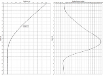
I need help to decide the embedment of caissons retaining a 17 ft wall. These 2.5 ft diameter caissons spaced 8ft on center. I have attached the schematic showing the wall and the deflection and moment diagrams with depth. The upper 6 ft consists of highly expansive clay and I am using Ka of 0.6 and below 6 ft I use Ka of 0.3. At about 10 ft we reach claystone bedrock. The unit weight for the bedrock is 120 pcf, friction angle of 26 degrees and cohesion of 450 psf.

I was thinking the wall should be minimum 35 ft long or 18 ft of embedment below excavation based on the deflection diagram.

Thanks
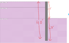
wall schematic.png
Deflection and Moment Diagrams.png
 
Replies continue below

Recommended for you

40 ft total height with 23 ft embedment seems not reasonable. The deflected shape implies 32 ft should be OK. Apparently you have modelled the cantilever portion with active soil loading but the embedded portion is not clear and could be with horizontal springs which are getting harder at lower depths.
 
Last edited:
40 ft total height with 23 ft embedment seems not reasonable. The deflected shape implies 32 ft should be OK. Apparently you have modelled the cantilever portion with active soil loading but the embedded portion is not clear and could be with horizontal springs getting harder with more depth.
So based on the plot what is a reasonable embedment ?
 
The deflected shape implies 32 ft should be OK. Apparently you have modelled the cantilever portion with active soil loading but the embedded portion is not clear and could be with horizontal springs getting harder with more depth.
Around 15 ft should be OK.
 
It all depends a LOT on the soil properties, magnitude of the soil lateral loads, water table conditions, loads on the upper earth level (adjacent footings, traffic, etc.) and the desired allowable lateral deflection at the top.

Just saying "about 15 ft. should be OK" isn't reasonable based on what information was provided in the original post.
 
For a wall such as this, I would recommend you check it by hand. Software can sometimes obscure how stable your wall is. To check the stability of the wall, determine the embedment depth at which the sum of moments due to active and passive earth pressures (and surcharge if present) about the base of the pile equal zero. This is the embedment needed for rotational equilibrium. For your final design, you should do this calculation with a reduction factor applied to the passive pressure. Say 0.5. This would give you a factor of safety of 2 with regards to overturning. Assuming you're using ASD to design the steel member, check your max pile moment based on unfactored earth pressures.

I hope this helps.
 
Bending moment and deflection diagrams should not be used to check embedment depths for a canti wall. You need to do a stability check
 

Part and Inventory Search

Sponsor