Continue to Site

Eng-Tips is the largest engineering community on the Internet

Intelligent Work Forums for Engineering Professionals

  • Congratulations MintJulep on being selected by the Eng-Tips community for having the most helpful posts in the forums last week. Way to Go!

Cantilever Moment Distribution

Status
Not open for further replies.

Robs1121

Structural
Oct 25, 2018
8
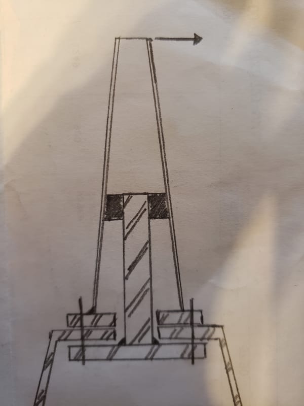
Is there a way to calculate the moment distribution between two cantilever pipes, one inside the other? Or some reference I can find this information? The exterior pipe is a tapered steel pipe with constant wall thickness and the interior steel reinforcement pipe is constant diameter and thickness. I want to determine if the interior pipe is designed to take 50% or near 50% of the load. I also want to design the interior pipe connections because they will be connected independently on their own support plate. I can not confirm what percentage of the load the interior pipe is taking. I calculate a distribution factor of (I1/L1)/((I2/L2)+(I1/L1)) as a relative stiffness percentage (59.1% exterior pole, 40.9% interior pole). I use an average I for my tapered pole between the bottom of the pole and the interior reinforcement pole connection (8'-0'' height). I wanted to confirm my calculation by modeling the pole in RISA. I modeled two separate ways, 1) I modeled the exterior tapered 25'-0'' pole as plates and the interior pole as a beam element and connected with rigid links at the top of the interior pole. The percentage increased with increasing load with an averaged percentage of about 20%(interior pipe) to 80%(exterior pipe). 2) The second method, I modeled the exterior tapered pole with 1'-0" sections stacked up to 25'-0'' using the calculated properties for each section. To model the interior pole, I modeled a single beam element (8'-0" tall) and offset a distance parallel to the load. Both beam elements are fixed at the base. I connected the pipes with a rigid link with both ends pinned. This model resulted in a distribution of 46% exterior to 53% interior pole. As you can see i am getting very different results from each methodology. What would be your procedure for calculating the relative stiffness for each pipe element?

I greatly appreciate your any input/direction
20210426_232619_wc9dpm.jpg
. Thank you.
 
Replies continue below

Recommended for you

What is this thing? What's the purpose of the inner and out tubes?

Working out precisely how much load goes to each will depend on a few different things that you can't know exactly. I'd just design it conservatively, e.g. design the outer tube to take all of it
 
Its various existing poles for lights, flags, and equipment towers. They are existing and its an idea for strengthing them. Some may have fatigue problems, its a general solution we are looking into.
 
You have to connect for the shear between the two pipes in order for them to act compositely... unless I'm missing the issue. or, is that a splice between the two tubes... then it's simply a matter of designing for the shear and moment connections between the two elements and there is no composite action. Constructability is another issue.

Rather than think climate change and the corona virus as science, think of it as the wrath of God. Feel any better?

-Dik
 
dik said:
You have to connect for the shear between the two pipes in order for them to act compositely

It looks sleeved? It's unlikely to be a perfect fit, and for such stocky elements the outer pipe may end up doing all the work before the inner pipe engages.
 
The top portion of the reinforcement is going to be wedged into the outer pipe, we are not looking for composite action, we just want to reinforce the base of the poles. I know there are other ways to reinforce the base of the pole but some jurisdictions may not want an added stiffener or reinforcement on the outside of the pole/base. We are working on different solutions to encompass all possible scenarios.
 
so the outer "pipe" takes all the load initially and deflects.

at some stage it'll bear against the inner "pipe".
and the two will share based on stiffness.

If you want anything close to "truth" it'll be FEA.

You could get close using a unit load on the inner pipe.

Do you Need the inner pipe to work ? Easier to make the outer "pipe" sufficient for the load applied and leave the inner "pipe" contact as "gravy" or redesign to remove contact.

another day in paradise, or is paradise one day closer ?
 
Status
Not open for further replies.

Part and Inventory Search

Sponsor