Continue to Site

Eng-Tips is the largest engineering community on the Internet

Intelligent Work Forums for Engineering Professionals

  • Congratulations cowski on being selected by the Eng-Tips community for having the most helpful posts in the forums last week. Way to Go!

Cantilever slab projecting from a slab?

Status
Not open for further replies.

MSUK90

Structural
Jan 29, 2020
155
Hello all.
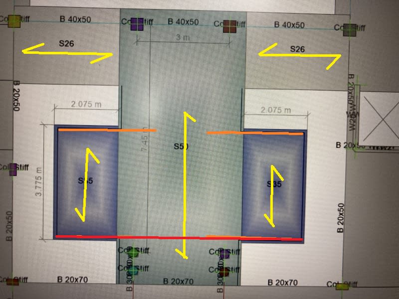
I was reviewing a concrete slab layout and would like to get your views regarding the load transfer mechanism here.
IMG_6252_vdq9ck.jpg


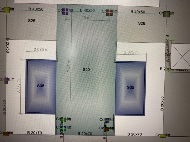
Will the cantilever slabs will be supported on the center slab here(this is what I presume)?
How much width of 500mm slab will be effective for carrying those slabs?
 
Replies continue below

Recommended for you

There are no columns under the S35 slabs so presumably they must cantilever. This warrants computer analysis in my opinion (probably quicker than hand as well when pattern loading and deflections are considered). But, if forced to do by hand, I'd use the strip method with two notional beams running down the edges of the S50 slab, say 1000 wide based on 2*distance from column centreline to slab edge (not dimensioned on your image so I've estimated from the dimensions given).
 
steveh49 said:
not dimensioned on your image
The distance from column center to slab edge is 550mm. So the width as per your recommendation will be 1100mm..
So I would design those 1.1m wide strips for normal moments from slabs and additional torsion from the cantilever slabs?
Also, cantilever slabs will be designed separately with fixed end right?
 
No need for torsion in the notional beams. Treat the cantilever slabs as having a backspan between the two notional beams - see the image.

Screenshot_20210218-203830_Box_aeog9k.jpg


This will stimulate the torsion in the S50 slab which will twist towards the loaded cantilever when only one is loaded. The nearer notional beam will deflect down and the opposite beam up just like the edges of the slab that the notional beams represent.
 
I got your view. I believe, based on the dimensions, my center slab will be in full tension throughout it's width.
The tension(top) bars should be continuous throughout in such situation I think.
 
I would run the bars all the way across as you said. As a practical matter, consider a lap in the middle of the S50 slab so any errors (tolerance) when cutting bars to length can be fixed by adjusting the lap length as needed. The specified lap length should be slightly longer than needed to make this work.
 
Thank you steveh49 for your views.
 
Agree with others above. Its quite straightforward - but watch your pattern loads.
 
I agree with the above comments..

I just want to add, this slab system should be modelled and analyzed with FEM . Apparently, the deflected shape of S 50 slab will be cylindirical and the S35 slab will follow that shape. That is, the cantilever moment of S 35 will accumulate at two sides ( shown with red at the following sketch) so the cantilever reinf. should also be concentrated at two sides and span reinforcement in longitudinal direction should be provided.

If i were the designer, i would calculate the total cantilever reinf. for 3.75 w and distribute the top reinf 1/3 at two sides and 1/3 at middle and provide bottom rebar in longitudinal direction ..

The following sketch is for working directions of the slabs..
IMG_6252_slab_working_direction9ck_wyyw3i.jpg
 
Status
Not open for further replies.

Part and Inventory Search

Sponsor