Continue to Site

Eng-Tips is the largest engineering community on the Internet

Intelligent Work Forums for Engineering Professionals

  • Congratulations MintJulep on being selected by the Eng-Tips community for having the most helpful posts in the forums last week. Way to Go!

Cap bank tripping

Status
Not open for further replies.

stevenal

Electrical
Aug 20, 2001
3,798
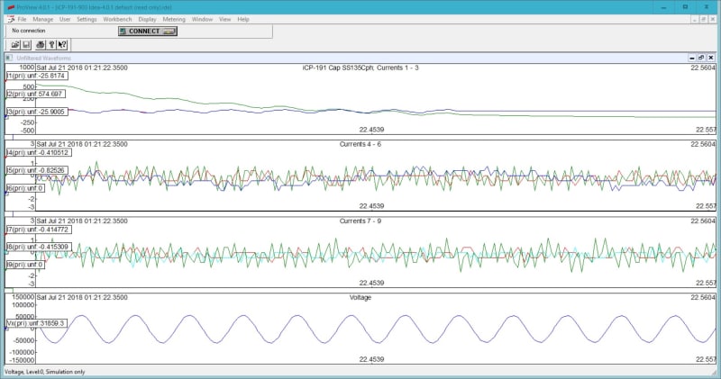
The image below is from a single phase cap bank relay. A prior event is nearly identical. Only the first three strings are in use, so please ignore currents 4 through 9. Strings 1 and 3 are perfectly matched as they should be, but string 2 current went high causing the bank to trip. String 2 remains high after tripping. Looks like all DC. Capacitor units were tested after the first event, and looked okay. The posted event occurred five days after re-energization. I believe it is measurement error, but wonder what situation would cause this. Any ideas? Thanks.
Untitled_mqtfyc.jpg
 
Replies continue below

Recommended for you

I'm confused. Are those voltage traces or current traces?
I don't understand the current persisting after the trip.
Is this three phases or three capacitor banks on one phase?

Bill
--------------------
"Why not the best?"
Jimmy Carter
 
Bill,
The graph on the bottom is bus voltage, all others are current. Ignore the middle two graphs.

The relay is monitoring three strings of current on the C phase of a three phase cap bank and C phase bus voltage to provide overcurrent and impedance tripping. Similar relays monitor the other two phases.

I also don't understand current persisting. Since the cans test okay, I suspect a measurement error. I'm not sure what CT problem would cause this, though. Either with the external CTs, or the CTs within the relay. I'm leaning toward a relay problem, though. What think?

Steve
 
Hello. Am I correct that the graph is showing about 12 cycles and the center is zero?
Is it possible that one relay has a problem with an offset zero?
That is, a failing relay?
Is it feasible to switch the relay with one of the other relays and see if the problem follows the relay?


Bill
--------------------
"Why not the best?"
Jimmy Carter
 
Autoscaling shifted the range up some. I1 and I3 combine to make the purplish line which ends up at zero. I2 starts at over 500 A positive ending up at around 100 A negative, so the DC offset is not constant.

Yes, that would be feasible. Also thinking of shifting center string to one of the unused inputs.
 
Status
Not open for further replies.

Part and Inventory Search

Sponsor