Eng-Tips is the largest engineering community on the Internet

Intelligent Work Forums for Engineering Professionals

Capacitor Charging

Status
Not open for further replies.

TugboatEng

Marine/Ocean
Nov 1, 2015
11,388
1
36
US
I have a circuit with a 270000uF electrolytic capacitor that gets charged direct online by a pair of 8D batteries at 24V. Is this something that I should consider some type of charging regulator for? I installed this system and found the supplying Cutler-Hammer 15 amp type BAB circuit breaker failed immediately afterwards. I don't know if the circuit breaker was previously faulty or if the inrush damaged it. This is a battery selection system which uses a voltage sensing relay to switch to a backup supply during a fault and the capacitor is to provide power during the changeover.
 
Replies continue below

Recommended for you

A pre-charge circuit consisting of a resistor in parallel with a switchable contact is probably needed while charging to limit the current. When beginning to charge, the contact is open and current is limited by the series resistor. When the capacitor is at around 95% voltage, the contactor closes and shorts around the resistor for normal operation. Search "capacitor pre-charge."

xnuke
"Live and act within the limit of your knowledge and keep expanding it to the limit of your life." Ayn Rand, Atlas Shrugged.
Please see FAQ731-376 for tips on how to make the best use of Eng-Tips.
 
There are real capacitor testers that will measure leakage and internal resistance.
Typically for a capacitor bank that size there would be some circuitry to limit the in-rush and discharge currents.
Otherwise the currents can get very high.

= = = = = = = = = = = = = = = = = = = =
P.E. Metallurgy, consulting work welcomed
 
The batteries provide nearly unlimited current availability.
The capacitor when discharged presents as a dead short.

You have the classical "when and immovable object is being hit by an unstoppable force" situation.

The solution is just a resistor and a parallel diode with the diode pointing back at the batteries.

This limits the "unlimited current availability" on the way into the cap but doesn't limit the current availability back out of the capacitor.

For a 15A breaker it's simply 24V / 15A = 1.6Ω of resistance or more.

For both the resistor and the diode you do need some power capacity.

The peak power that drops exponentially thru the resistor starts at 15A[sup]2[/sup] x 1.6Ω = 360W ouch!
If you can take a few seconds to precharge then a 10Ω resistor changes this to:
24V / 10 = 2.4A
2.4A[sup]2[/sup] x 10 = 57W

100W 10 Ohm

For a diode you don't say what the draw out of the cap might be so here's a hefty unit I'd use.
It's a bridge rectifier which you don't need but it's simple as hell to use, easy to mount, isolated unlike stud diodes, and spade-luggable.
Rectifier Diode 50 A 1000 V
Hook either or both "~AC" terminals to the capacitor side and then use only the "+" side back towards the batteries.


Keith Cress
kcress -
 
I dissected the failed circuit breaker and the weld that attaches the conductor to the bi-metallic strip had broken. The closing spring became the conductor, got hot, and annealed itself which prevented the breaker from closing.

I have not had an issue with tripping, the circuit breaker failure just raised concern about inrush. I saw no signs of burned contacts or overeating of the conductors, only the spring. I think this breaker had failed earlier.

I have experienced that the inrush is high enough to cause a power transfer with battery voltage at 26.0V and the transfer set to occur at 24.0V. Wiring is mostly 10 gauge, about 40 feet of it. In service I will likely set the transfer to occur at 21V but I haven't tested to see if there is still issue.

These breakers are not DC rated and I understand the difficulties of breaking DC but there shouldn't be serious arcing when making low voltage DC even against a dead short?

Otherwise, the system is working and I want to expand it to cover the rest of my fleet but without introducing new problems. I will provide a diagram tomorrow.
 
Not reducing capacitor inrush just because some testing circuit worked isn't a very good reason to continue that practice into production equipment. You will have troubles caused by it, especially if you deploy enough systems doing that.
 
Do electrolytic capacitors have any limit on maximum current? I've not seen any listed in data sheets. Does ESR and high current do bad things? I'm guessing that the multiple foil wraps result in a good distributed resistance.
 
Personally I wouldn't assume either the capacitor or the breaker is suitable for this kind of service (energizing large cap without any current limiting) unless it was verified in the catalogue (maybe it's part of some UL listings, I don't know).

I'm not a system designer but fwiw my impression the original setup sounds dangerous. Typically breakers for switching large capacitors do have some kind of switching resistors built in. Like Lionel said, maybe your setup works a few times... until it doesn't.

Keith's idea sounds like a good one to me

=====================================
(2B)+(2B)' ?
 
Does equivalent series resistance play a role in charging current during a step change? The particular capacitor I am using has an ESR of 9 ohms at 100kHz + 20°C.

Considering this is my first time building such a circuit, I sized the capacitor very generously. I used a 2 volt drop over 1 second at an expected max load of 10 amps. The advertised switching time of the relay is 35ms. If I were to reduce the size of the capacitor would there be a certain point where I would not need a charging circuit?
 
9 ohms, that sounds encouraging to me for current limiting. It might be fine for all I know. It might also be that the 9 ohms at 100khz is dominated by skin effect and you'd have much lower effective resistances at lower frequencies like 10khz (an step change has a wide range of frequencies). It's unknown for me (like I said I'm not a system designer). Maybe you or someone else here knows more about it than me.

=====================================
(2B)+(2B)' ?
 
The ESR puzzle was that 9 Ohms of it would have dropped the current far more than the .009 Ohms would. It was the belief in the ESR not the facts of the ESR that was problematic.
 
Yeah!
47ipbn4.gif


When I saw 9Ω I was thinking Tug must've used a Leyden Jar.

Even 0.009Ω x 24V = 2.7kAmps which is likely still a bit hard on that $10 breaker's contacts.

Keith Cress
kcress -
 
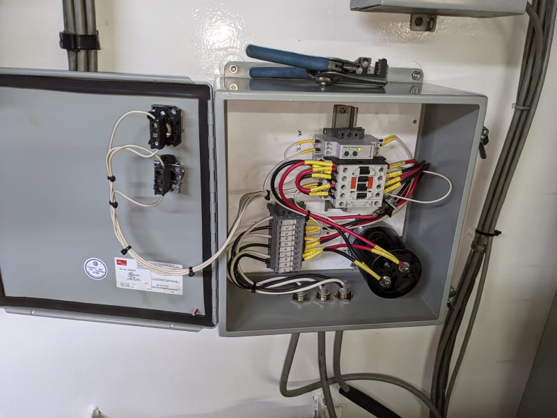
The Cutler-Hammmer BAB is supposedly a thermal-magnetic trip. I can't find much documentation on it. Should it not trip on mag if the current were actually that high? It's not tripping during close. In fact. I used DIN terminals with a disconnect tab and I manually closed that and hardly got a spark. It doesn't behave like it's spiking with that much current. If primary power is closed first the capacitor charges through a diode. If the secondary is closed first the main contactor closes to charge the capacitor.


PXL_20220428_225916788_erqojb.jpg


I promise I'll make a diagram. I will also make a diagram that includes the suggestions proposed here.
 
Status
Not open for further replies.
Back
Top