Continue to Site

Eng-Tips is the largest engineering community on the Internet

Intelligent Work Forums for Engineering Professionals

  • Congratulations MintJulep on being selected by the Eng-Tips community for having the most helpful posts in the forums last week. Way to Go!

Capacitors for Voltage Support 1

Status
Not open for further replies.

Cerkit

Electrical
Jan 18, 2016
100
Hi.

How do Capacitors provide Vars when connected to a power system. And why does this help increase the voltage in areas of low Voltage. I can't get an intuitive understanding. Please can you help.

Thanks
 
Replies continue below

Recommended for you

Capacitors in parallel with inductive loads locally provide at least some of the reactive current component that is needed by the inductive load. Since the source no longer has to produce this reactive current component, a smaller overall current can flow through the line from the source to the load, producing a smaller voltage drop, and thus raising the end-of-line voltage.

xnuke
"Live and act within the limit of your knowledge and keep expanding it to the limit of your life." Ayn Rand, Atlas Shrugged.
Please see FAQ731-376 for tips on how to make the best use of Eng-Tips.
 
It becomes very clear when you draw out the vectors on a simple voltage drop calculation with a single impedance element.

Conductors are mostly reactive so let's just assume Z=X*i.

Your voltage drop will be V1-V2 = V1 - I*Z.

If you assume the load current I is very lagging, I = IL<90 deg, the greatest voltage magnitude drop across a reactor is going to be due to reactive current. V<0 - I<90*X<90 = (V-IL*X)<0.

Likewise, if you have capacitive current ,IL<-90, V<0 = (V+IL*X)<0. The "voltage drop" increased or there was a voltage step up. The capacitive current caused a voltage increase the conductor.

It all makes sense when you draw out the vectors.

Improving the PF of the current will also improve the voltage drops across the system if it reduces the currents. A load with a PF of 0.8 can reduce the amount the current it draws as it improves its PF towards 1.0. A load with a PF of 0.8 is drawing 25% more current than it needs theoretically needs to.


------------------------------------------------------------------------------------------
If you can't explain it to a six year old, you don't understand it yourself.
 
Any time electrons flow through wires, the moving electrons create magnetic fields, which results in stored energy. Each half of a power system cycle, this reactive energy must be temporarily stored elsewhere as the magnetic fields fully discharge and then recharge in the opposite polarity. Capacitors provide a nearby location to temporarily store the reactive energy in the electric field. As reactive energy flows between inductors and capacitors, the electrons encounter two kinds of effects that result in voltage drop: 1) resistance is the result from not having a perfect conductor, 2) reactance is the result of the moving electrons creating a magnetic field around the wire. If no capacitors are present, the reactive energy must instead travel all the way back to the generator every half cycle. In the actual power grid, capacitors are spread throughout the grid in the form of power factor correction capacitors at various voltage levels as well as the capacitance of cables and wires.
 
Back to basics folks.
Remember the series XC circuit?
The voltage across the capacitor may exceed the applied voltage, sometime by quite a bit.
The capacitors will form a series circuit with the supply transformer. If the value of the capacitors is great enough, the voltage may rise above the supply voltage.
Back in the day when PF correction was more art than science and bulk correction was commonly used, we had to be aware of the effect and be careful that we did not leave too much capacitance connected under light load conditions.
Too much bulk correction left on-line when a plant shut down for the night could result in widespread lamp failures.
All the art went away when PF correction controllers became economical.

Bill
--------------------
"Why not the best?"
Jimmy Carter
 
Customers may not be aware that removing capacitors from service during light load periods is precisely what utilities do, meaning that the effects of in-plant power factor correcting capacitors will vary inversely as the impedance between the grid and the cap, and thus not every customer will necessarily experience lamp failures due to high system voltage.

As you often say, Bill, it depends.

CR

"As iron sharpens iron, so one person sharpens another." [Proverbs 27:17, NIV]
 
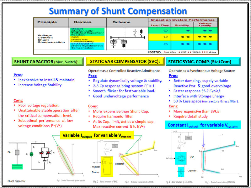
Significant improvement in power quality can be achieved using power electronic base switching technology better known as Flexible AC Transmission System (FACTS).
Below are pros & conns of shunt compensation applicable for HV systems.
Shunt_Compensation_ux63u0.jpg
 
Hi,

If I have a regular distribution feeder with low voltage and I use a capacitor to improve the voltage, where on the line would it have to for maximum utilisation and would it improve voltage for both customers before and after the location of the capacitor?

Thanks
 
It depends!


Bill
--------------------
"Why not the best?"
Jimmy Carter
 
Cerkit said:
If I have a regular distribution feeder with low voltage and I use a capacitor to improve the voltage, where on the line would it have to for maximum utilisation and would it improve voltage for both customers before and after the location of the capacitor?
The voltage rise is directly proportional to capacitor current and line reactance (see cuky's link), so it will be greatest at the end of the line. Yes, the voltage will rise for all customers even if the capacitors are not at the end.

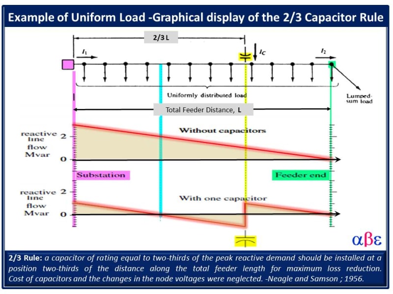
You should also consider line losses. Capacitors will reduce line losses if they are located correctly. Line losses depend on total line current, not just the capacitor current. If you put the capacitors beyond the load, there will be more line current and losses in the line sections between the load and the capacitors. There is an optimum capacitor location along the line that depends on the load distribution along the line. Theoretically determining the optimum location is difficult. The best thing to do is model the circuit with a distribution analysis program and try different capacitor locations.
 
Although it is a standard utility practice to use capacitors for voltage compensation in MV and HV, It is uncommon for low voltage feeder regulation.

Due to the relatively short length of LV feeders, appears reasonable to consider the use of capacitors as close as possible of the inductive load (ex. large motors or Industrial load) and consider using alternate option to adjust the voltage such as using a buck-boost transformer, change the transformer tap, large feeder size, etc.

Below is a common practice used in general application in the power industry to locate the capacitor in a radial feeder:


Capacitor_Optimal_Location_-_two_third_Rule_kmju1f.jpg
 
Hi,

Thank you it's starting to make a lot more sense now.

Regards
 
Status
Not open for further replies.

Part and Inventory Search

Sponsor