Eng-Tips is the largest engineering community on the Internet

Intelligent Work Forums for Engineering Professionals

Capacitors on a motor for air compressor

Status
Not open for further replies.

cavitate

Civil/Environmental
Aug 12, 2008
53
0
0
US
My son brought home from his workplace 4 AC capacitors used on the motor of an air compressor.
The air compressor will not spin but is trying.
There has been a wire that shorted against the case of one of the 50uF caps, this did burn a hole in the case and some of the oil leaked.
Since the cap measures the correct value, I wonder if that is the problem.
Could the cap measure perfectly fine, but not work under load at higher voltages than the Cap checker?

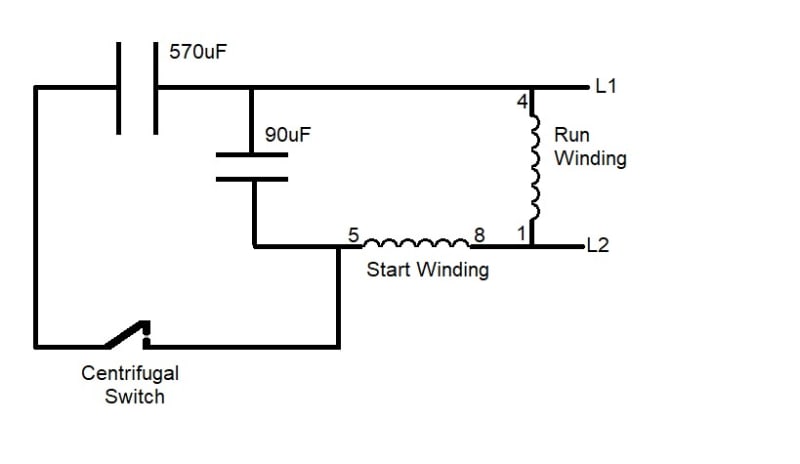
The wiring of the 4 caps seems quite odd to me, two 50uF caps in parallel and two 1150uF caps in series and then these are in series. I'm thinking it was a repair, BUT, my son says the 4 caps seem to fit in the original enclosure.
I'll post a drawing of the way the caps are wired below.
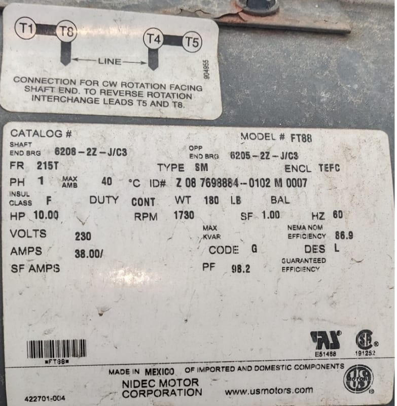
BTW, If the cap wiring makes since, can some draw or point me at a schematic to show me where the 3 wires go in the motor? (T5, T6 and blank)
Thanks, Mikek
P.S. I'm kinda wondering if the centifugal switch is open, and the start winding is not energized.
We will replace the leaky cap as the first attempt.
 
 https://files.engineering.com/getfile.aspx?folder=8c09da6c-c82e-47df-b0be-ab60153a7d14&file=Motor.png
Replies continue below

Recommended for you

Capacitors can read good, but with full voltage have a short. This is because there could be a puncture in the dielectric.
I can not open the file.
So the total capacitance would be 600uF.
If you spin the motor by hand then energize the motor then does it start? If so that would be a problem in the starting winding/path. Maybe you need the capacitors and the starting switch.
 
The round-round flat-flat would be indicative of this being a setup for a Cap-Start/Cap-Run motor design, in which case that wiring is wrong.


" We are all here on earth to help others; what on earth the others are here for I don't know." -- W. H. Auden
 
>>So the total capacitance would be 600uF.

I get 100uF in series with 575uF or 85uf.
Mikek

>>The round-round flat-flat would be indicative of this being a setup for a Cap-Start/Cap-Run motor design, in which case that wiring is wrong.

I said the same to my son, he said two of us looked it over and made the drawing.
But, I'm thinking the drawing is also wrong.
btw, if they remove the belt from the motor it does run. (no load on the motor)
Mikek
So, being that I am the smartest person in the room, re: this, which is not saying much, it may be up to me to get this thing wired up correctly,
without benefit of knowing how it was originally wired. So, I need more info, I suspect, but don't know, this is a motor with a centrifugal switch.
The motor is on a two piston air compressor. A schematic showing the winding connections would help.
I will try to get more info about the motor today, brand, model number, etc.
Thank, Mikek
 
Does the compressor have an unloader and is the unloader working?

--------------------
Ohm's law
Not just a good idea;
It's the LAW!
 
>>Does the compressor have an unloader and is the unloader working?
I don't know, I'll try to get more info.
Mikek
 
I have attached a picture of the motor nameplate, much larger motor than I thought, 10 HP.
Here's a motor description.
Mav_s_motor_Plate_jt9peg.jpg


I called the company and ask for a diagram, they said they would email it to me, 30 minutes and I haven't received it yet.
Mikek
 
The caps have been replaced and it did not fix the problem, I'm saying check the centrifugal switch.

However to I'd like to know if I have any understanding of the motor operation.
Here's the general schematic.
Motor_Mike_s_Question_qcnbcm.jpg


When power is first applied the Centrifugal switch is closed, all the current for the Start Winding must go thru
the 570uF and the 90uF capacitor, this causes a small phase shift, when the motor gets close to full speed, the centrifugal switch opens
and the current for the Start Winding flows only in the 90uF cap causing a larger phase shift.

OR, is the phased shift unimportant and it is just the higher current in the start Winding when the Centrifugal switch is closed
(because of low Xc)and then in run (when the switch is open) it has a lower current reduced by the higher Xc of the 90uF cap?

Thanks, Mikek
 
The capacitors supply reactive current to the start winding.
The demand for reactive current is much greater when starting than when running at speed.
More capacity in the start circuit means more more reactive current available when starting.

--------------------
Ohm's law
Not just a good idea;
It's the LAW!
 
I understand reactance causes a phase shift, I also understand when the centrifugal switch is closed the capacitors look like 4Ω in series with the start winding and when the switch opens the capacitive reactance increases to 29.5 Ω in series with the start Winding.
So, when the motor is starting and the switch is closed, the current through the start winding is higher because of the reduced reactance of the larger capacitance, and then, when the higher torque to start the motor is no longer needed, the lower reactance (larger capacitor) is removed (switch is opened) and the current in the start winding is lower for run mode.

I guess my confusion is about the phase shift. It may be that the phase shift is small and not important to the motor operation and it is just the series reactance that alters the current depending on if the switch is open or closed.
But it could be the phase shift that sets the direction of rotation.
Any thoughts?
Thanks, Mikek
P.S. any idea what the reactance of a start winding in a 10HP motor is?
Also it probably varies on the load on the motor or if the rotor is locked.
So lets say right at start up, what is a reactance of the start winding?
I know my questions are usually somthing no one knows about or cares about,
but I'm still curious.


That's a 3 phase motor link.

Yes, start winding+start cap does provide 90 phase shift to enable starting of single phase motors, whose flux is pulsating, not rotating. Without this phase shift, the single phase motor won't start.

Buy a cheap LCR meter from Amazon (under 50 bucks are available) to measure inductance and calculate the reactance.

Muthu
 
The capacitors create a phase shift that, with the angular displacement of the start winding relative to the main winding, generates the starting torque.
How many degrees?
Enough to start the motor.
Have you looked at The Cowern Papers?
This link should start a download.

--------------------
Ohm's law
Not just a good idea;
It's the LAW!
 
>The capacitors create a phase shift that, with the angular displacement of the start winding relative to the main winding,
>generates the starting torque.
>How many degrees?
>Enough to start the motor.

Seems to me the phase shift would set the rotation direction, but the higher current in the Start Winding when the centrifugal switch is closed would provide the additional torque required to start.
Comments?

>Have you looked at The Cowern Papers?
>This link should start a download.
>
I have not seen it, I but have downloaded it and will read it.
I have an electronics background but never got a good understanding
about electric motors. Even though, I could troubleshoot many problems.

Thanks, Mikek

EDIT, reading part of the PDF, page 7 describes the motor I'm concerned with.
My question, after the motor has started and hits 75% of rated and speed the Centrifugal switch is open, the start winding is still energized through a smaller capacitor.
Is the smaller capacitor still required, to produce a phased shift? Is a phase shift required at this point or would the motor run OK without a phase shift and the cap is simply there to reduce the current on the smaller wire gauge used for the Start Winding. In my case the 100uf capacitor has 26Ω of reactance, That limits the start winding current to 9amps, but it is even less because of the start winding inductance adds vectorally to the 26Ω.
 
The start winding is displaced 90 degrees to the run winding. The capacitor creates an electrical phase shift to go with the physical displacement.
Once the motor is up to speed, there is no further need for the start winding.
In a capacitor start winding, the capacitor is cut out completely by the centrifugal switch.
Leaving the start winding connected with some capacitance adds some extra torque to the motor.
Reversing the connections to the start winding reverses the phase shift and thus starts the motor in the opposite direction.
You must consider the impedance of the start winding circuit to calculate the current.
The impedance is composed of the winding resistance acting at right angles to the difference between the capacitor reactance and the winding reactance.
To make it more fun, the winding reactance may vary over approximately a 6:1 range between locked rotor and full load.

--------------------
Ohm's law
Not just a good idea;
It's the LAW!
 
@ waross,
The starting winding is left on the circuit as per the drawing posted by the OP. Only the additional starting capacitor is switched off when the motor reaches full speed.
 
If I add;
"capacitor start/run motor"
to this sentence?
"Leaving the start winding connected with some capacitance adds some extra torque to the motor."
Sorry for the confusion.

--------------------
Ohm's law
Not just a good idea;
It's the LAW!
 
The diagram is correct for a CS/CR motor, and yes, the AUX winding remains in the circuit, only the Start Capacitor is switched out. But if the centrifugal switch is stuck open, it will not start with just the Run capacitor in place, you need the phase shift caused by the bigger cap. That's the usual failure mode, because the motor was up and running, when some sort of crud or debris got into the centrifugal switch so when they shut down, the contacts never re-closed. Seen it many times. You might try spraying come contact cleaner into the NDE bell where the centrifugal switch is, then tap it with the back of a screwdriver for a few minutes. Beyond that, you need to disassemble the motor to get to the centrifugal switch.


" We are all here on earth to help others; what on earth the others are here for I don't know." -- W. H. Auden
 
The problem was the contacts of the centrifugal switch. I theorize and it's probably right, that a wire shorted against the housing of one of the capacitors, Clear signs of this, a hole burned in the case of the cap and oil leaked out. When the wire shorted, this produced an over current and burned the contacts of the centrifugal switch. The two contacts of the centrifugal switch are in series, it just happens that there is a spade lug
on the switch assembly that allowed bypassing the burned contact. So the wire was moved to bypass the burned half of the centrifugal switch and the motor works fine. Although the leaky cap was replaced.
Thanks for the help, Mikek
 
The motor will start with just the run capacitor, as compressors are started unloaded. The run capacitor is needed for the extra torque required when the pressure builds toward maximum.
 
Status
Not open for further replies.
Back
Top