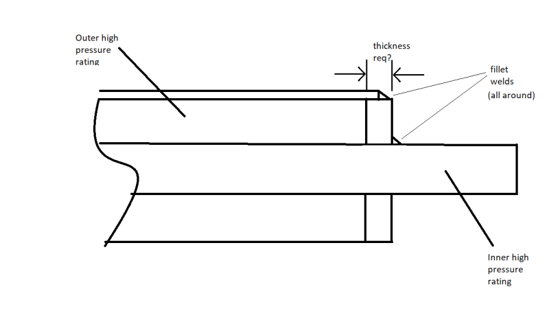
I'm trying to calculate the required thickness on an end cap for our vessels and I was looking for a way to do this. I've been using ASME sec VIII div I UG-34 for the design of flat heads, but the issue is that this end plate has a concentric pipe that is bored out of it.
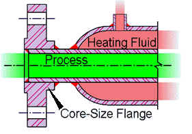
The end plate is essentially a large washer that is single fillet welded at the ID of the jacket pipe and the OD of the inner pipe.

The simple relationship I've found for the minimum end cap thickness is t=d*sqrt(CP/SE) , where d is the end cap diameter, C is the attachment factor from UG-34 (0.33 I'm assuming), P is design pressure, S is allowable stress, and E is joint efficiency (I'm assuming 0.7 for partial RT).
I'm not sure if I can simply use an equivalent diameter relationship to account for the area differential from a full end cap or if I need to go through a more extensive calculation process. Conservatively, not accounting for the inner pipe at all, I get a min thickness of almost an inch, which goes down quite a bit if I use an equivalent diameter or hydraulic diameter instead for variable "d".
Thanks in advance for any advice!
The end plate is essentially a large washer that is single fillet welded at the ID of the jacket pipe and the OD of the inner pipe.

The simple relationship I've found for the minimum end cap thickness is t=d*sqrt(CP/SE) , where d is the end cap diameter, C is the attachment factor from UG-34 (0.33 I'm assuming), P is design pressure, S is allowable stress, and E is joint efficiency (I'm assuming 0.7 for partial RT).
I'm not sure if I can simply use an equivalent diameter relationship to account for the area differential from a full end cap or if I need to go through a more extensive calculation process. Conservatively, not accounting for the inner pipe at all, I get a min thickness of almost an inch, which goes down quite a bit if I use an equivalent diameter or hydraulic diameter instead for variable "d".
Thanks in advance for any advice!


![[bigsmile] [bigsmile] [bigsmile]](/data/assets/smilies/bigsmile.gif)