Continue to Site

Eng-Tips is the largest engineering community on the Internet

Intelligent Work Forums for Engineering Professionals

  • Congratulations KootK on being selected by the Eng-Tips community for having the most helpful posts in the forums last week. Way to Go!

Carport structure

Status
Not open for further replies.

VentengInfo

Structural
May 3, 2019
7
I am designing a carport (frame) to accommodate solar panels that must have a 30 degree in slope. Each bay must fit 2 cars ~ 7m x 4m, with the lower height 2.5m. What would be the best structural approach:

[ol 1]
[li]a frame with HSS for the columns, 30 degrees sloped I beam for the rafters and C channels for the purlins, versus [/li]
[li]a frame with HSS for the columns, 0 degrees I beam for frame perimeter, 30 degrees OWSJ and channels for the purlins [/li]
[li]other [/li]
[/ol]

Has anyone designed a similar structure (carport)? Would concrete foundations, using sonotubes/bolts for the base plate, support reactions?

Thanks for the feedback.

Regards,
Ventenginfo
 
 https://files.engineering.com/getfile.aspx?folder=feafe8d1-3bf3-4d29-967a-965e8f82954a&file=carport.png
Replies continue below

Recommended for you

I think what you have shown in the attachment looks pretty cool. I’ve done a design almost exactly like that except without the diagonal columns. For the foundations, combined footings like you have shown is the best way to go to reduce the required footprint of the footing for wind uplift. If you want to elevate the columns above the footing you can put them on plinths/sonotubes as you mentioned. With the steep slope you might consider using smaller HSS tubes for the purlins since you should be able to get gravity and wind uplift loads to work without needing any bracing between purlins at midspan, which you might need for the channels. Kind of depends if the framing is exposed or if there’s a soffit.
 
Hi txeng91,
Thanks for the feedback, what I beam profile did you used? and HSS? The frame is exposed. Thanks again.

 
These are a couple links to how I see them done here. Not sure how applicable they are to your situation but I thought the ideas might be helpful.

Here's one I saw yesterday. It's got a slope to it but less than 30°. What I like about this one is the limited intrusion into the parking areas. Seems like the posts/concrete wall near the ends would constantly be removing car mirrors.

Tempe Library

This one's got a bit more slope - but it's not a double deep scenario.

32nd St. Phoenix

If you want to browse some of the more exotic/taller structures, take a look at the parking lots around Arizona State University.

ASU 1

ASU 2


Thanks azcats,

These are amazing structures. ASU1 is exactly what I was thinking in my option 1, then ASU2 is my option 2. Very good to see both types built. I was not sure if the options that I thought was a good idea.

I can't see very well in the picture but, I am assuming that on ASU1 they connected the column to the beam is using a top plate adding the required stiffeners. What do you think about this connection?

Thanks for the feedback.
 
I think that connection needs to do a lot of work with the square footage of wind area. But it appears to be an extended end plate moment connection probably designed per AISC Design Guide 4. No reason it couldn't accommodate the loads required if properly designed.
 
VentegeInfo

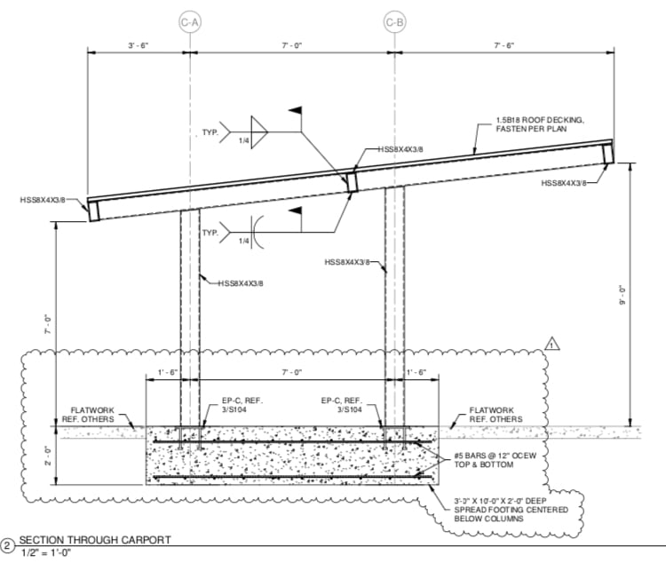
See attached section. Can’t say I love it and it’s pretty expensive but this is what they wanted. It’s all welded up tube members.

B21336E4-0B65-4924-8B44-026FEBD36736_axrsau.jpg
 
That Tempe library looks pretty impressive!

Agreed that (limited) intrusion of the columns is a major factor. Whatever route you choose, don't go for slenderness but take collisions into account.
 
That's great, thanks for sharing the section.

I am running a qualitative analysis of some structural options and the attached configuration has the minimal horizontal reactions:

New_Picture_2_gnuhco.jpg


For the foundation, I can't go very deep because it's near a lake and water level is around -1.5m. I will do something similar for the foundation.

As you had a contractor welding in place, I am assuming that your connection with the column was welded too?
 
I will probably reduce my slope to 10 degrees, the above was 30 degrees.

I just did a simulation with regard to the solar panels efficiency, and at 10 degrees it reaches 90% of the maximum solar efficiency in my location (around 34 degrees in slope to have maximum kWh from solar)
 
Status
Not open for further replies.

Part and Inventory Search

Sponsor