Continue to Site

Eng-Tips is the largest engineering community on the Internet

Intelligent Work Forums for Engineering Professionals

  • Congratulations KootK on being selected by the Eng-Tips community for having the most helpful posts in the forums last week. Way to Go!

Cartridge Plate sandwiched between Body Flanges

Status
Not open for further replies.

cak4Engg

Petroleum
Jun 13, 2015
19
Hi Guys,

Do we have to perform any additional calculations when two body flanges sandwich a support plate for filters?
[ul]
[li]The app-2 calculation was performed for body flanges.[/li]
[li]and support plates were evaluated for Differential pressure and cartridge weight.[/li]
[/ul]

As the configuration is similar to Figure UHX-12.1 (d), is it logical to perform calculations as per UHX?

Body flanges sandwich a support plate
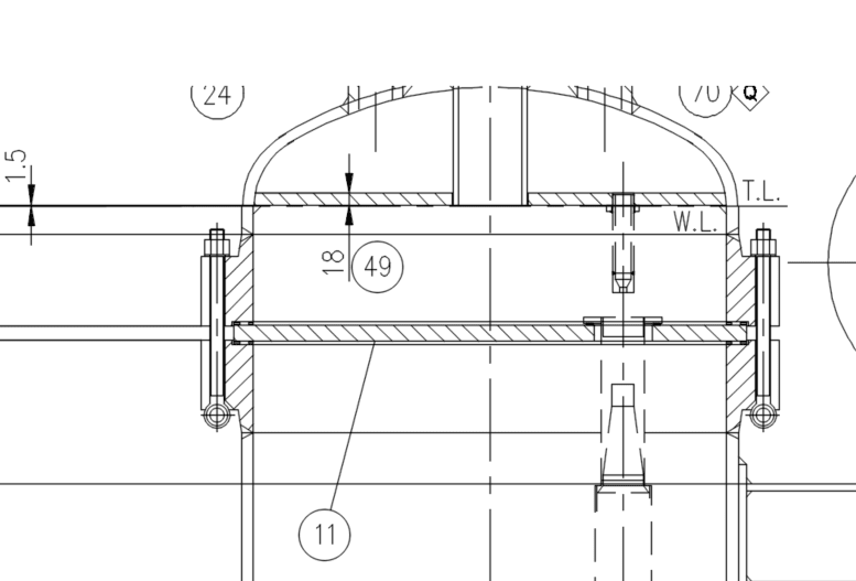
Plate_Sandwiched_betwen_BFs_or1kkk.png


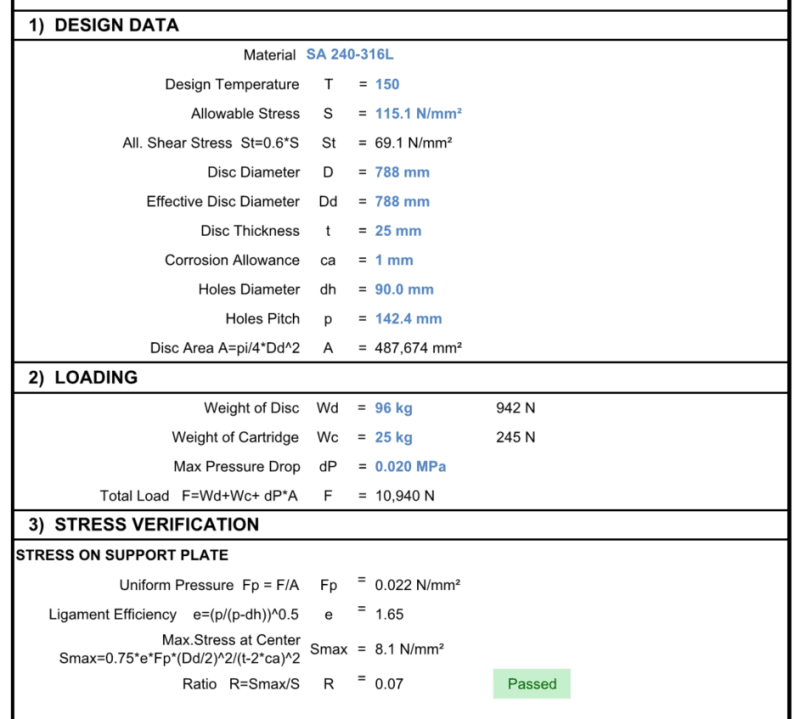
Calculation for support plate
Support_Plate_calculation_bdmljp.png
 
Replies continue below

Recommended for you

Ligament efficiency greater than one. How interesting.

I doubt Part UHX calculations would be of any interest, but perhaps you need to satisfy yourself.

Regards,

Mike

Edit: I guess it makes sense given the context, Smax

The problem with sloppy work is that the supply FAR EXCEEDS the demand
 
cak4Engg

1) For the support of the filter consult the fabricator.
2) You are very confused, contact a pressure vessel engineering

Regards
 
@SnTMan
Yes sir, the description of that term needs to be changed to something else.
It is indeed confusing.

@r6155
If you could give me any code reference or any guidance on how code has addressed similar scenarios (item-11, in the drawing), then that would be a real help, rather than typing obvious things on the technical discussion.
 
Your "support plate" is generally called a "tube sheet" . that name should give internet information.
 

@blacksmith37
Thanks for the reply, are you suggesting to use UHX chapters for the design?

This configuration is similar to Figure UHX-12.1 (d),
 
"and support plates were evaluated for Differential pressure and cartridge weight"

Presume this diff press is the bursting differential pressure for the filter (data from filter element vendor) plus a healthy margin - say 50%, so total diff press = 1.5x filter bursting dp? This way, there is no danger of the support plate buckling when any filter element bursts due to plant operator negligence of operating limits. Right now, all you have is 0.02Mpa (3psi), which may most likely be the normal operating unfouled diff press. Bursting dp may be more like 50psi??
 
@ cak4Engg
Did you read the link I sent you?

Regards

 
@r6155, the link is not relevant and doesn't answer the OP's question.
 
@ RaymondN
Let (OP) decide if it's relevant or not.
What is your help?

Regards
 
Hi r6155,

Honestly, it doesn't answer my question.
Anyway thanks for sharing.
 
@georgeverghese,

Thanks for the response, This was the Max. Diff Pressure advised by the filter vendor but I do agree to your logic.
Filter element busting pressure should be taken in to account.

I Hope The way I have addressed this issue is right.
If any have you guys have come across similar designs, please do share.

I am also planning to perform FEA to evaluate the same, based on the assumption that the above scenario is out of code rules.
 
cak4Engg
You did not answer my questions. If you don't read you won't be able to understand.
Did you consult the filter manufacturer?
Did you read the link?
With the little information received, I can anticipate that its design is wrong. At that diameter the shell flanges could be removed. It depends on the product to filter.

Regards
 
r6155, a bit more friendly would help at times. You’re quite offensive as of lately. Are you Dutch by the way?

Huub
 
Thanks you XL83NL. Im not dutch.
"If you get a response it's polite to respond to it" (as said litteinch).
But until now it has not happened by (OP),since 29 Jun and 12Jul

Regards


Details and Diff.pressure is provided by the filter vendor.

@r6155,

I am not able to understand what you are trying to say here.
If you are trying to help, please respond to the following,

1. is there any code reference for a sandwiched support plate (as shown above fig)?
2. As the configuration is similar to Figure UHX-12.1 (d), is it logical to perform calculations as per UHX?
3. "At that diameter, the shell flanges could be removed" at what diameter? why the body flanges have to removed?
4. If you have you ever come across similar designs, please do share.

If you can't, please stay put...


@cak4Engg,

UHX-12.1(d) evaluation where you convert the weight and cartridge loading as additional to differential pressure with some generous margin might satisfy you and your Client.
I would also consider Roark's calculation for circular plates (with consideration of ligament efficiency) as additional evaluation from UHX and limit the deflection on the plate.
 
I think it would be better that you calculate the body flange and the support plate separate.
The support plate just use the bending stress with hole in it,you can caculate acc to UG-39 & UG-53,
Body flange acc. to App-2.
UHX 12.1-(d) have tube in,your structure have no tube,it just like a flat head with hole.
 
@RaymondN & Tiger_Wu,

Thanks for sharing your views.

 
Status
Not open for further replies.

Part and Inventory Search

Sponsor