Eng-Tips is the largest engineering community on the Internet

Intelligent Work Forums for Engineering Professionals

Cartridge Valve Explain please 1

Status
Not open for further replies.

moobe

Electrical
Apr 27, 2010
29
0
0
MD
Hello all,

I have this valve.Can some explain to me . How it works. When A coil is energized and the B coil is energized and when in the centre position. The input at the cartridge valve is the pressure input from the pump. Does oil from the cartridge valve flow from A to B when the valve is in the centre position


cartidge_valve_oe41sn.jpg
 
Replies continue below

Recommended for you

Based on what is shown, when the valve is centered all ports are connected together. Fluid will flow from P, pressure, to T, tank. Port B is blocked so there will be no flow out port B. Port A is blocked by the 160 bar relief valve so no flow out port A.

Ted
 
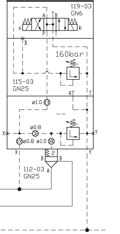
There seem to be a lot of A and B ports in the drawing. To be clear, I think we're talking about the ones at the bottom of the drawing (The Cartridge valve's A and B).

The way I read it, the valve is fed from the A port, and works to control pressure upstream on the A line by selectively dumping flow to B.

With the DCV deenergised, the top chamber on the cartridge is vented to tank through the open centre of the DCV (with supply pressure dropped across the 0.8 mm orifice that'sin line with the bottom X port. This will allow the poppet in the cartridge to lift, dumping the A port to B.

With coil a energised, all flow through the top two blocks of the stack ceases. Pressure on the top of the poppet is now controlled by the set pressure of the relief valve in the bottom of the stack, and the cartridge valve will lift sufficiently to dump enough flow from A to B to limit the pressure in the A line to a fixed value defined by the setting of that relief. I think this only makes sense if the relief in the bottom block is set to a higher pressure than 160 bar.

With coil b energised, the pressure at the top of the poppet is controlled to 160 bar (assuming that the relief in the bottom block is set to a higher value than that), limiting pressure in the A line to 160 bar.

So it looks like a solenoid operated pressure maintaining valve, with settings of a: a value adjustable above 160 bar, b: 160 bar and otherwise 0(ish) bar.

A.
 
Hi,
Thanks for your reply. I am not a hydraulic guy but please excuse me If I am stupid

"With the DCV de-energised, the top chamber on the cartridge is vented to tank through the open centre of the DCV (with supply pressure dropped across the 0.8 mm orifice that'sin line with the bottom X port. This will allow the poppet in the cartridge to lift, dumping the A port to B."

Could you please explain. Why will the cartridge lift? Since all the oil is being dumped to the tank. I am sorry but I am trying to understand. Could you explain to me why different orifices are used?. I am no means a hydraulic guy. I would appreciate if you could explain to me
 
The poppet in the cartridge has the pressure from the A port (on the cartridge valve) on one side and pilot pressure (from the dashed line on the schematic) on the other. Depending on which force (note I said force and not pressure since this depends on the area that the pressure acts on) is greater, the valve will either be open or closed. There's also a spring in that valve to bias the valve towards being closed if the forces are nearly equal (such as when the pressure at port A is zero).

So in this case, with the directional valve in the center position, the pressure on top of the poppet will be the tank pressure (likely zero) and the pressure on the bottom will be the pressure at the A port. So assuming that the pressure at A is some significant value, the net force on the poppet will move it and cause the valve to open.

As far as the orifices are concerned, to my knowledge (which is admittedly limited) they are typically used to adjust how quickly the valve reacts. Smaller orifices will restrict the speed that fluid flows through them and will cause the valve to react more slowly.

Don't worry about not knowing this stuff, everyone has to start somewhere. If you want to know more, here's a decent primer on cartridge valves: CHAPTER 11: Slip-in Cartridge Valves (Logic Valves)
 
The position of the poppet depends on the difference in pressure between the top and the bottom - when the pressure in the bottom is greater than the pressure in the top, the poppet lifts, exposing the B ports in the side of the valve bore, and starting to connect A to B. Key points here are that all the stuff in the upper part of the drawing only ever sees pilot flows; the only reason it's there is to control the pressure on the top of the cartridge valve and that port on the top of the cartridge is a dead end - it sees no steady flow at all. Finally, when the whole lot is working properly, the cartridge valve will open only just enough to balance the pressures - it isn't a bang-bang device.

So why will the poppet in the cartridge lift when the dcv is de-energised? Because the conditions at the top of the drawing leave zero pressure on the top of the cartridge. On the assumption that there's an external pump feeding the A port and that there's nowhere much else for the flow from that pump to go, then that will generate positive pressure in the A port. Because that positive pressure on the bottom of the valve is greater than the zero on the top, the poppet will lift (the spring that's drawn on the top of the poppet is usually very light indeed).

So what about the orifices? It's worth looking at these in two groups. Your tally says you're "electrical", so it might just be easiest to think of the 0.8 mm orifices as if they were resistors and the reliefs as if they were zeners. The 1.0 mm orifices are a little bit different. Although I said that there's zero flow into the top of the cartridge valve, that was only true in a static sense - there's a little bit of in and out to make up for the change of volume in the top chamber as the poppet moves up and down. The 1.0 mm orifice in the line going to that chamber just helps to damp the movement of the poppet and stops it fluttering. I think the other 1.0 mm orifice acts to stabilise the 160 bar relief in a similar manner.
 
addon: @stick's point about forces rather than pressures being balanced in the cartridge valve is a valid one. I was assuming equal areas above and below which is often, but by no means always, true.

A.
 
moobe, which symbol are you calling the cartridge valve? Is this not a representation of a manifold with several cartridge valves installed or integral to the manifold?
Do you have a manufacturer's model number and specification document?
Are there other components off to the right of the image?

Ted
 
Thanks for the explanation guys. Fantastic. This forum has some many knowledgable persons
@hydtools . I am referring to the one with the that looks like a pencil point
 
If I apply pressure to Port B of the cartridge valve, Can flow occur from B to A. What condition will cause flow from B to A ? Or is it always A to B for this circuit
 
Obviously you could apply pressure on the B port, but I don't think it would do anything useful. Why? Partly because all the pilot tappings are on the A side, so unless there is some sort of independent pressure source on the A side, the poppet will stay obstinately shut. If you do apply a bit of A side pressure, then the desired flow from B will increase the A-side pressure, forcing the cartridge valve even further open. I'm not sure what sort of benefit you'd get from this kind of positive feedback behaviour.

A.
 
Status
Not open for further replies.
Back
Top