-
1
- #1
Hi,
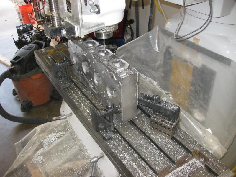
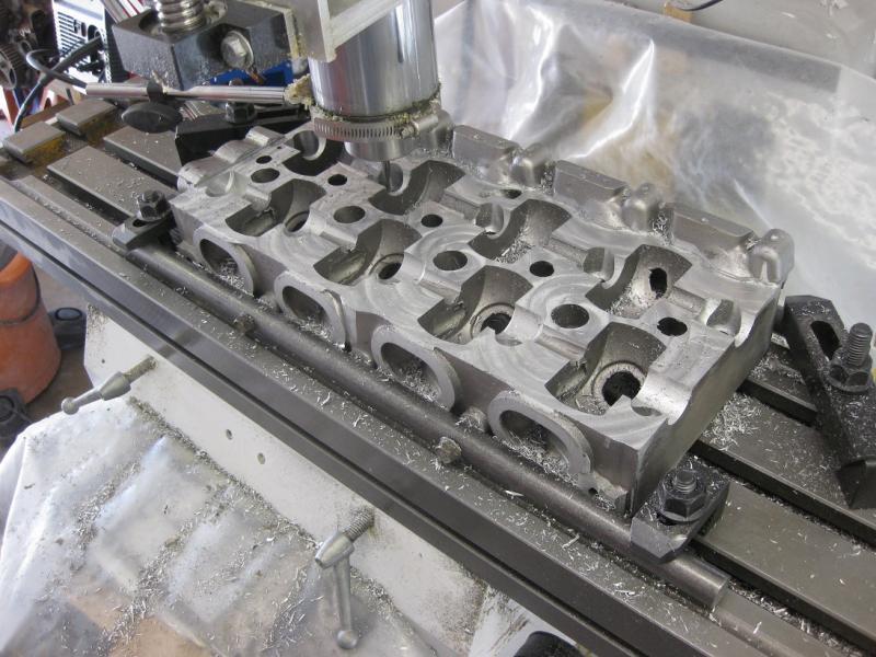
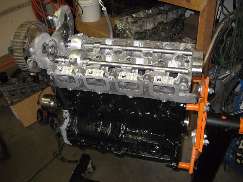
I am developing an automotive cylinder head for which I am doing all the foundry work for the prototype. I am having some pretty serous issues with core blows mainly from the water jacket. I have developed casting experience/processes which I have used to produce other simpler, cored castings, with excellent results.
1st Casting
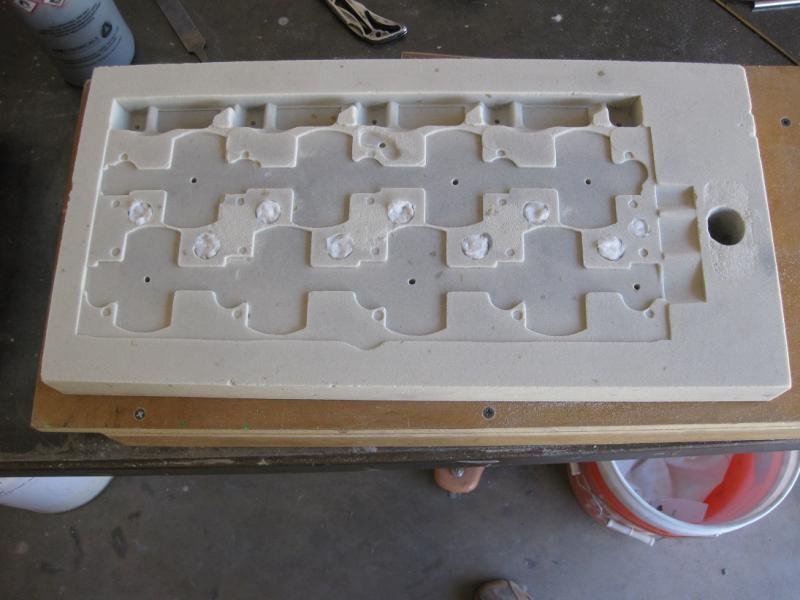
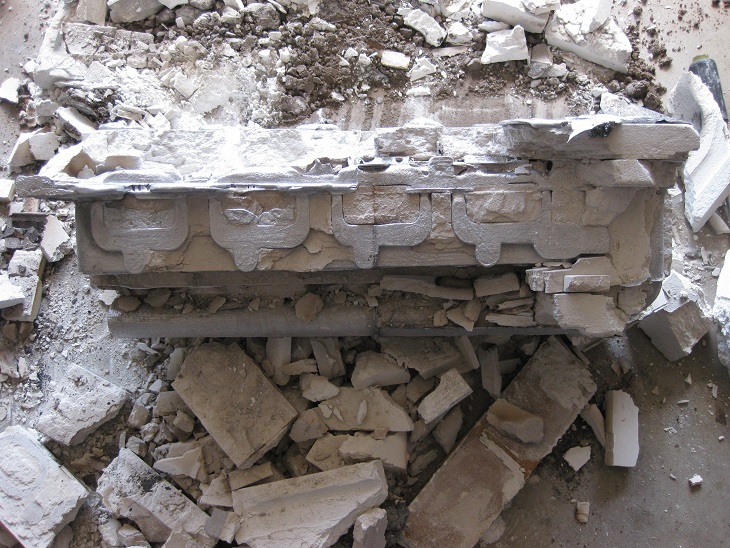
The casting alloy used was scrap re-melted cylinder heads (so probably alloy 319 maybe 356). A quality 319 ingot will be used once I get the process down. Plenty a flux was used and degassing was preformed by bubbling argon gas injected to the bottom of the crucible. I used a powder bed 3-D printer to make molds/cores with a home brew plaster based powder concoction and had overall disastrous results partly because the molds did not stay together.
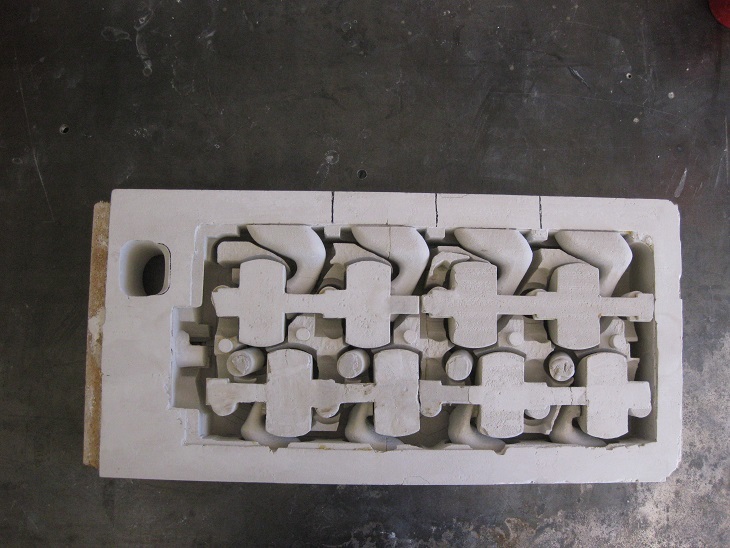
2nd Casting
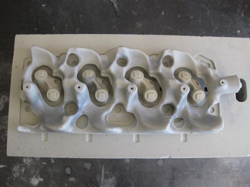
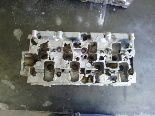
I then used traditional patterns/core boxes and # 85 silica sand for both the molds and most of the cores using Pep Set three part resin for the binder. For the water jacket core I tried 3-D printing again to avoid making a core box do to its complexity. The results were disastrous due to extreme core blows from the binders I used in the plaster. Here is a picture
3rd - 4th Casting
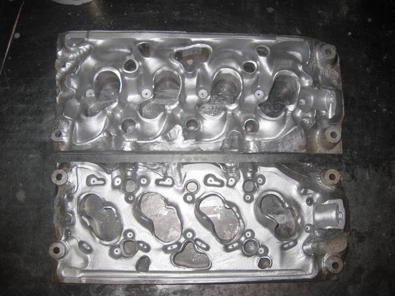
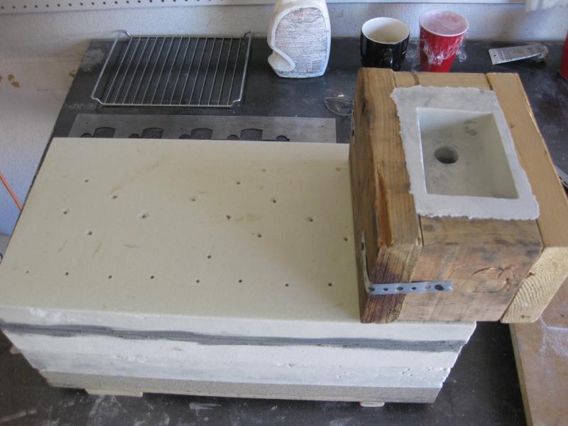
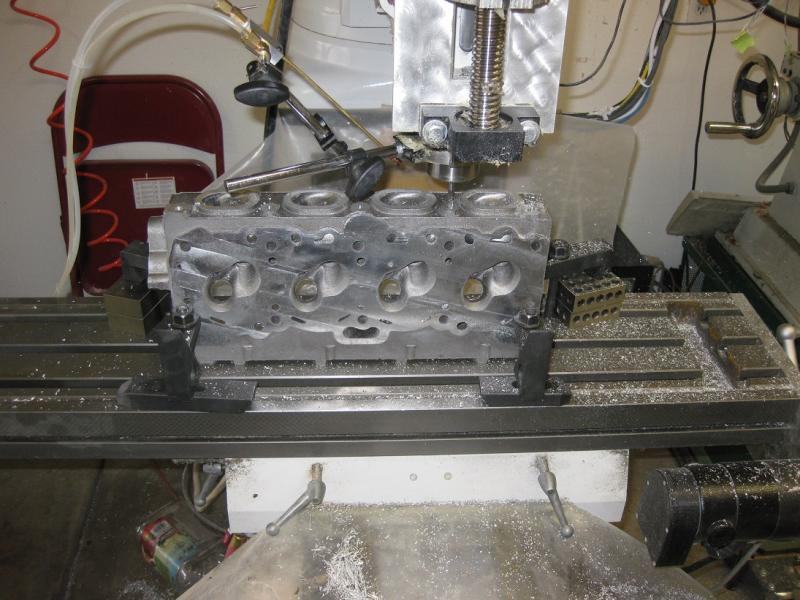
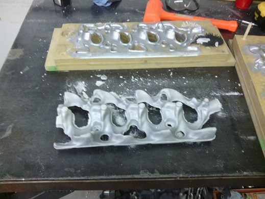
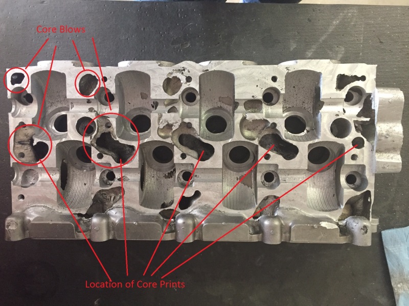
In these iterations I made the water jacket core using a traditional pattern and #85 sand and sodium silicate binder set with CO2 gas. I used sodium silicate for the water jacket core in hopes of an easier core shakeout as it somewhat dissolves with water. For the other mold and core pieces I used the same #85 sand and Pep Set binder. The results were still disastrous as it was evident after inspection that the top vent holes and surfaces solidified first as expected but the core gasses in the water jacket continued to build displacing the still molten metal. Here is a picture of the water jacket core and the casting after machining.
5th Casting
This time I tried using sodium silicate as the binder for all the mold and core pieces setting it with CO2 gas. I had a little better results but still unacceptable core blows. The pour temperature was 1350 deg F. Here is a picture of the casting.
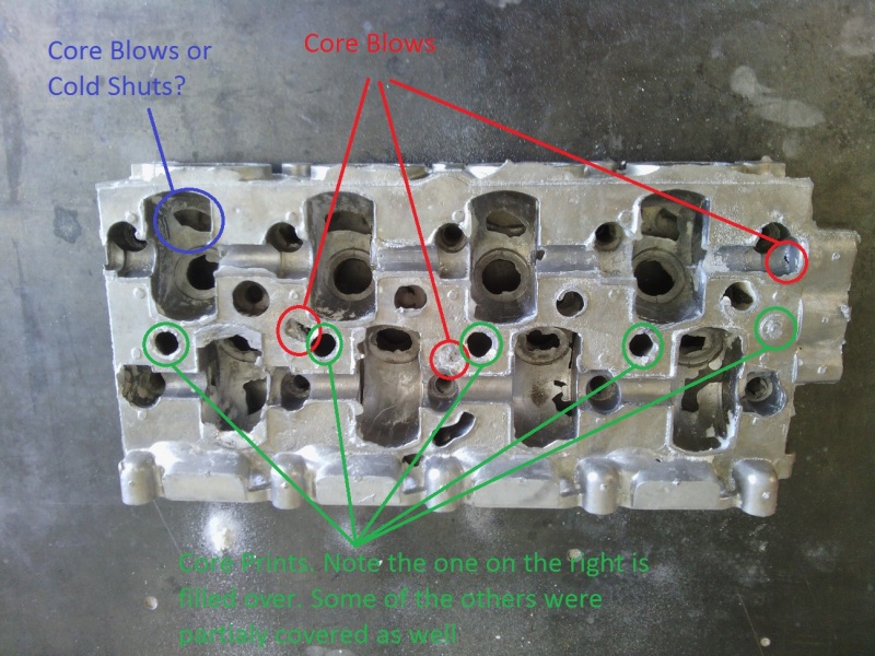
6th Casting
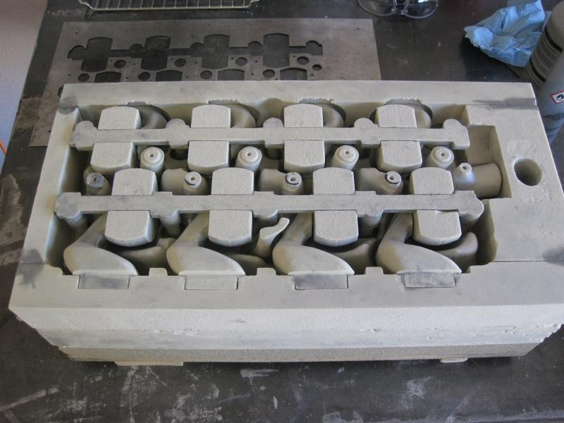
This last casting to date I used #30 silica sand for the water jacket core to improve gas permeability and made a gasket out of ceramic insulating blanket and placed it on the core prints to help prevent metal from blocking their venting properties. I also poured at 1200 deg F to give less time for core gasses to build.
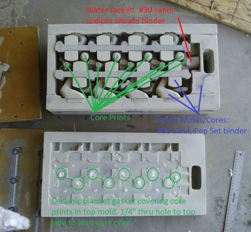
This time I did not get any core blow defects on the top surface (as seen by non-destructive visual inspection). However, this time I did get core blows on the bottom of the casting right were the bottom feeding gates are, which was unusual and did not happen with previous castings.
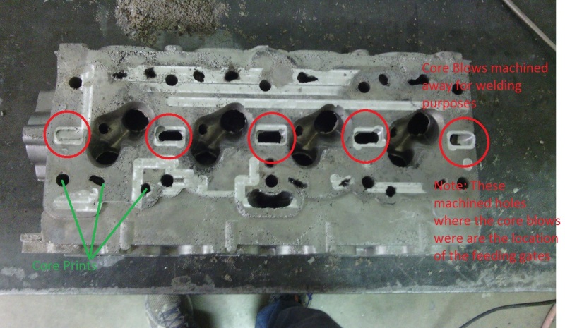
During this casting as well as some of the others, there were some gasses that burbled up from the pouring sprue during and after pouring. One theory I have is that it did not result in any core blows in the bottom portion of the casting for previous castings because the higher pour temperature for the others allowed the metal to remain molten and gasses to rise to the top.
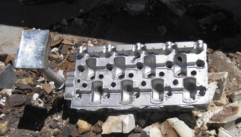
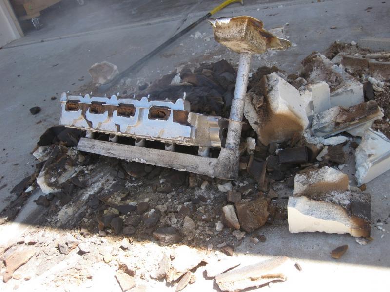
Here is a picture of the casting with the runner and sprue attached. The cross section of the runner and gates are about 2" x 1.25" and 1" x 1.25" respectively.
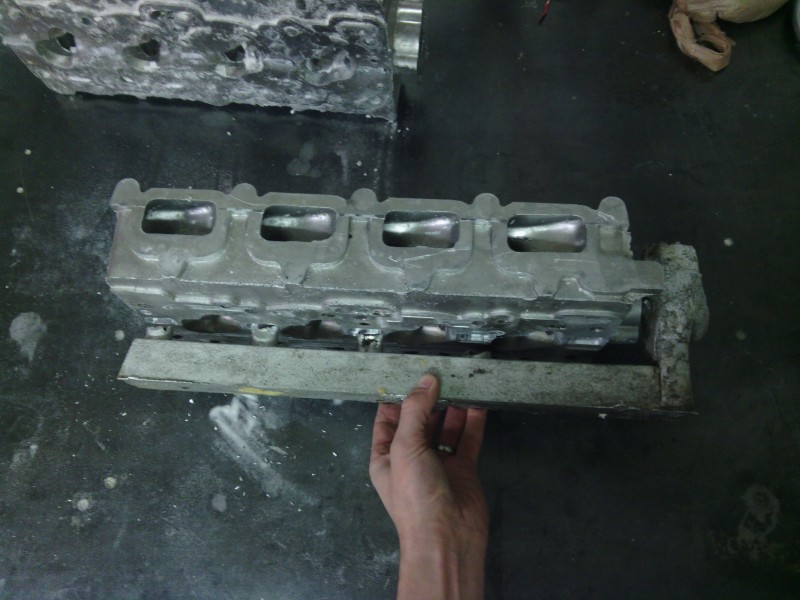
Since the bottom of the head is the thickest the idea was to feed the casting from the bottom so as to setup a top down directional solidification with a large cross section runner that would solidify last and act as a feeder. This has apparently been working as I have not had any issues with shrinkage or hot tearing (except one area that has some slight shrinkage and tearing which I am confident can easily be remedied by a simple design change - reducing cross sectional area in that spot). I am open to other gating ideas. I placed ziped .stp file of the mold assembly on my website here Link. There is a slight difference in that the cross section of the runner in the CAD model is oval and the actual pattern I made is rectangular. Additionally the water jacket core in the .stp assembly is not correct. The correct one is the waterjecket_sculpted_final.stl.
Any advise on what to try next or resources to learn from are welcomed. I am stumped as to what to try next. Here are some ideas I have.
-Bake the water jacket core to get rid of any residual moisture.
-Use another type of sand binder. If so what?
-Use a courser sand for the outer molds for additional gas permeability. Size suggestions?
-Add additional core prints for the water jacket core on the sides to aid in venting. The design constraints will not allow for larger or additional core prints on the top.
Thanks,
Adam
I am developing an automotive cylinder head for which I am doing all the foundry work for the prototype. I am having some pretty serous issues with core blows mainly from the water jacket. I have developed casting experience/processes which I have used to produce other simpler, cored castings, with excellent results.
1st Casting
The casting alloy used was scrap re-melted cylinder heads (so probably alloy 319 maybe 356). A quality 319 ingot will be used once I get the process down. Plenty a flux was used and degassing was preformed by bubbling argon gas injected to the bottom of the crucible. I used a powder bed 3-D printer to make molds/cores with a home brew plaster based powder concoction and had overall disastrous results partly because the molds did not stay together.


2nd Casting
I then used traditional patterns/core boxes and # 85 silica sand for both the molds and most of the cores using Pep Set three part resin for the binder. For the water jacket core I tried 3-D printing again to avoid making a core box do to its complexity. The results were disastrous due to extreme core blows from the binders I used in the plaster. Here is a picture

3rd - 4th Casting
In these iterations I made the water jacket core using a traditional pattern and #85 sand and sodium silicate binder set with CO2 gas. I used sodium silicate for the water jacket core in hopes of an easier core shakeout as it somewhat dissolves with water. For the other mold and core pieces I used the same #85 sand and Pep Set binder. The results were still disastrous as it was evident after inspection that the top vent holes and surfaces solidified first as expected but the core gasses in the water jacket continued to build displacing the still molten metal. Here is a picture of the water jacket core and the casting after machining.


5th Casting
This time I tried using sodium silicate as the binder for all the mold and core pieces setting it with CO2 gas. I had a little better results but still unacceptable core blows. The pour temperature was 1350 deg F. Here is a picture of the casting.

6th Casting
This last casting to date I used #30 silica sand for the water jacket core to improve gas permeability and made a gasket out of ceramic insulating blanket and placed it on the core prints to help prevent metal from blocking their venting properties. I also poured at 1200 deg F to give less time for core gasses to build.

This time I did not get any core blow defects on the top surface (as seen by non-destructive visual inspection). However, this time I did get core blows on the bottom of the casting right were the bottom feeding gates are, which was unusual and did not happen with previous castings.

During this casting as well as some of the others, there were some gasses that burbled up from the pouring sprue during and after pouring. One theory I have is that it did not result in any core blows in the bottom portion of the casting for previous castings because the higher pour temperature for the others allowed the metal to remain molten and gasses to rise to the top.
Here is a picture of the casting with the runner and sprue attached. The cross section of the runner and gates are about 2" x 1.25" and 1" x 1.25" respectively.

Since the bottom of the head is the thickest the idea was to feed the casting from the bottom so as to setup a top down directional solidification with a large cross section runner that would solidify last and act as a feeder. This has apparently been working as I have not had any issues with shrinkage or hot tearing (except one area that has some slight shrinkage and tearing which I am confident can easily be remedied by a simple design change - reducing cross sectional area in that spot). I am open to other gating ideas. I placed ziped .stp file of the mold assembly on my website here Link. There is a slight difference in that the cross section of the runner in the CAD model is oval and the actual pattern I made is rectangular. Additionally the water jacket core in the .stp assembly is not correct. The correct one is the waterjecket_sculpted_final.stl.
Any advise on what to try next or resources to learn from are welcomed. I am stumped as to what to try next. Here are some ideas I have.
-Bake the water jacket core to get rid of any residual moisture.
-Use another type of sand binder. If so what?
-Use a courser sand for the outer molds for additional gas permeability. Size suggestions?
-Add additional core prints for the water jacket core on the sides to aid in venting. The design constraints will not allow for larger or additional core prints on the top.
Thanks,
Adam

