Hi,
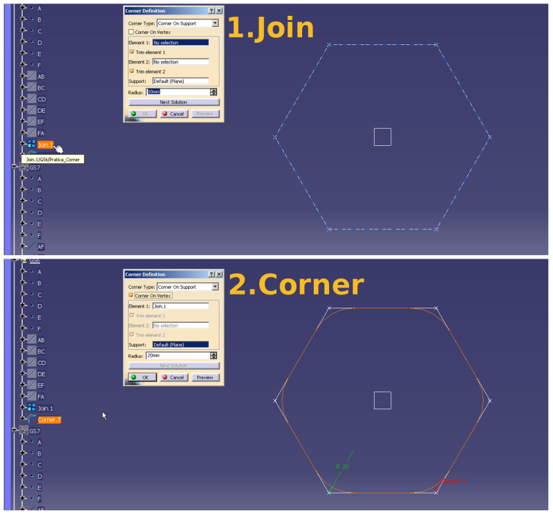
I'm working on a macro to automate the corner creation in a sharp-edge geometry.
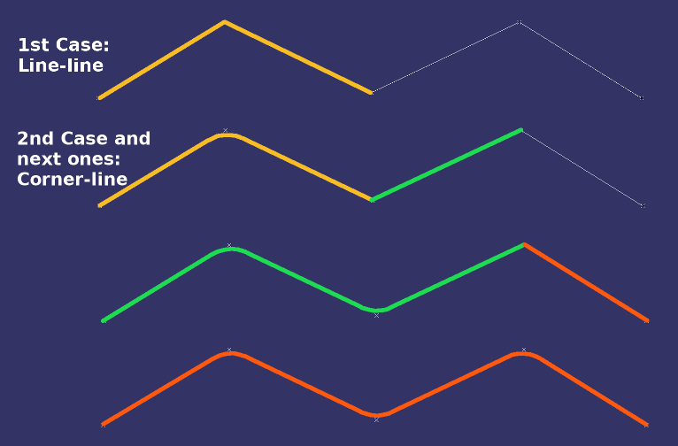
From previous attempts, I noticed that the parameters of the corner can vary, according to the references employed to create the corner - please check the code examples down below.
Then I'm looking for information on how CATIA sets the parameters to create the corner, in order to include this logic in my macro. Then, the macro shall be able to add corners like seen in the image:

Does anyone know how to automate the parametrization of the corner?
Thanks in advance,
Portolon
-----
Code Examples:
These parameters were recorded when a corner was added manually between two lines:
Dim hybridShapeCorner1 As HybridShapeCorner
Set hybridShapeCorner1 = hybridShapeFactory1.AddNewCorner(reference1, reference2, Nothing, 12#,[highlight #FCE94F] 1, 1,[/highlight] True)
hybridShapeCorner1.DiscriminationIndex = 1
hybridShapeCorner1.BeginOfCorner = 1
[highlight #FCE94F]hybridShapeCorner1.FirstTangentOrientation = 1[/highlight]
[highlight #FCE94F]hybridShapeCorner1.SecondTangentOrientation = 1[/highlight]
hybridShapeFactory1.GSMVisibility reference1, 0
hybridShapeFactory1.GSMVisibility reference2, 0
hybridBody1.AppendHybridShape hybridShapeCorner1
part1.InWorkObject = hybridShapeCorner1
And these parameters were recorded when a corner were added between a corner and a line:
Dim hybridShapeCorner2 As HybridShapeCorner
Set hybridShapeCorner2 = hybridShapeFactory1.AddNewCorner(reference3, reference4, Nothing, 12#,[highlight #FCE94F] 1, 1,[/highlight] True)
hybridShapeCorner2.DiscriminationIndex = 1
hybridShapeCorner2.BeginOfCorner = 1
[highlight #FCE94F]hybridShapeCorner2.FirstTangentOrientation = 1[/highlight]
[highlight #FCE94F]hybridShapeCorner2.SecondTangentOrientation = 1[/highlight]
hybridShapeFactory1.GSMVisibility reference3, 0
hybridShapeFactory1.GSMVisibility reference4, 0
hybridBody1.AppendHybridShape hybridShapeCorner2
part1.InWorkObject = hybridShapeCorner2
part1.Update
And another example of parameters from a corner were added between a corner and a line:
Dim hybridShapeCorner4 As HybridShapeCorner
Set hybridShapeCorner4 = hybridShapeFactory1.AddNewCorner(reference7, reference8, Nothing, 12#, [highlight #FCE94F]-1, -1,[/highlight] True)
hybridShapeCorner4.DiscriminationIndex = 1
[highlight #FCE94F]hybridShapeCorner4.BeginOfCorner = 2[/highlight]
[highlight #FCE94F]hybridShapeCorner4.FirstTangentOrientation = -1[/highlight]
[highlight #FCE94F]hybridShapeCorner4.SecondTangentOrientation = -1[/highlight]
hybridShapeFactory1.GSMVisibility reference7, 0
hybridShapeFactory1.GSMVisibility reference8, 0
hybridBody1.AppendHybridShape hybridShapeCorner4
part1.InWorkObject = hybridShapeCorner4
part1.Update
I'm working on a macro to automate the corner creation in a sharp-edge geometry.
From previous attempts, I noticed that the parameters of the corner can vary, according to the references employed to create the corner - please check the code examples down below.
Then I'm looking for information on how CATIA sets the parameters to create the corner, in order to include this logic in my macro. Then, the macro shall be able to add corners like seen in the image:

Does anyone know how to automate the parametrization of the corner?
Thanks in advance,
Portolon
-----
Code Examples:
These parameters were recorded when a corner was added manually between two lines:
Dim hybridShapeCorner1 As HybridShapeCorner
Set hybridShapeCorner1 = hybridShapeFactory1.AddNewCorner(reference1, reference2, Nothing, 12#,[highlight #FCE94F] 1, 1,[/highlight] True)
hybridShapeCorner1.DiscriminationIndex = 1
hybridShapeCorner1.BeginOfCorner = 1
[highlight #FCE94F]hybridShapeCorner1.FirstTangentOrientation = 1[/highlight]
[highlight #FCE94F]hybridShapeCorner1.SecondTangentOrientation = 1[/highlight]
hybridShapeFactory1.GSMVisibility reference1, 0
hybridShapeFactory1.GSMVisibility reference2, 0
hybridBody1.AppendHybridShape hybridShapeCorner1
part1.InWorkObject = hybridShapeCorner1
And these parameters were recorded when a corner were added between a corner and a line:
Dim hybridShapeCorner2 As HybridShapeCorner
Set hybridShapeCorner2 = hybridShapeFactory1.AddNewCorner(reference3, reference4, Nothing, 12#,[highlight #FCE94F] 1, 1,[/highlight] True)
hybridShapeCorner2.DiscriminationIndex = 1
hybridShapeCorner2.BeginOfCorner = 1
[highlight #FCE94F]hybridShapeCorner2.FirstTangentOrientation = 1[/highlight]
[highlight #FCE94F]hybridShapeCorner2.SecondTangentOrientation = 1[/highlight]
hybridShapeFactory1.GSMVisibility reference3, 0
hybridShapeFactory1.GSMVisibility reference4, 0
hybridBody1.AppendHybridShape hybridShapeCorner2
part1.InWorkObject = hybridShapeCorner2
part1.Update
And another example of parameters from a corner were added between a corner and a line:
Dim hybridShapeCorner4 As HybridShapeCorner
Set hybridShapeCorner4 = hybridShapeFactory1.AddNewCorner(reference7, reference8, Nothing, 12#, [highlight #FCE94F]-1, -1,[/highlight] True)
hybridShapeCorner4.DiscriminationIndex = 1
[highlight #FCE94F]hybridShapeCorner4.BeginOfCorner = 2[/highlight]
[highlight #FCE94F]hybridShapeCorner4.FirstTangentOrientation = -1[/highlight]
[highlight #FCE94F]hybridShapeCorner4.SecondTangentOrientation = -1[/highlight]
hybridShapeFactory1.GSMVisibility reference7, 0
hybridShapeFactory1.GSMVisibility reference8, 0
hybridBody1.AppendHybridShape hybridShapeCorner4
part1.InWorkObject = hybridShapeCorner4
part1.Update

