Navigation
Install the app
How to install the app on iOS
Follow along with the video below to see how to install our site as a web app on your home screen.
Note: This feature may not be available in some browsers.
More options
-
Congratulations waross on being selected by the Eng-Tips community for having the most helpful posts in the forums last week. Way to Go!
You are using an out of date browser. It may not display this or other websites correctly.
You should upgrade or use an alternative browser.
You should upgrade or use an alternative browser.
Catia Coordinate Dimension Table 2
- Thread starter CAD2015
- Start date
- Status
- Not open for further replies.
-
1
- #2
- Thread starter
- #3
Hi Iscariot,
Thanks for you prompt reply.
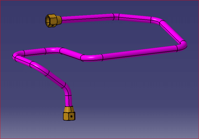
I have an assembly:

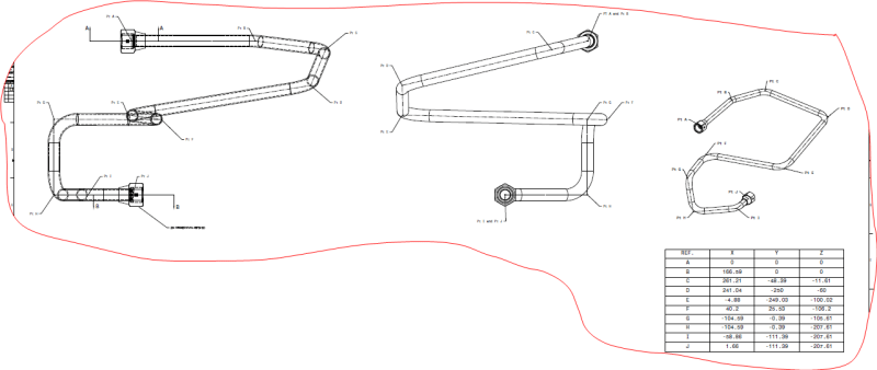
The task is clear: I need to create a drawing from it.
The ISO View in drawing would contain the chart/map of the points from 3D (please, see the picture use as a reference, in the first message).
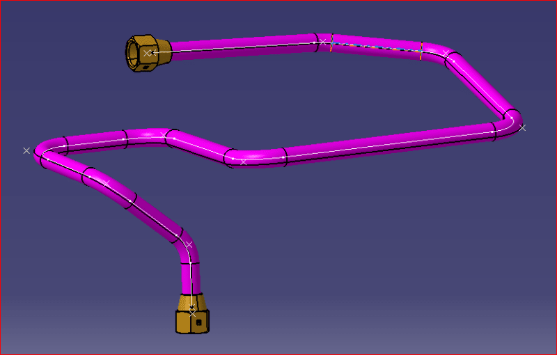
The 3D Assembly has its curves/points used for the pipe(tube):

What I want is to create a 2D representation of the pipe on the 2D drawing, for manufacturing reason.
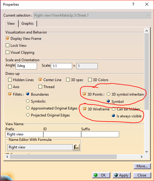
I did find an option: show the points and guide in 3D, then updating the views on 2D (making sure to check 3D Points and 3D Wireframe boxes in the view properties):

Also, I have to "Lock" the view.
But I wanted to know if there is a different method.
Thanks a lot!
Thanks for you prompt reply.
I have an assembly:

The task is clear: I need to create a drawing from it.
The ISO View in drawing would contain the chart/map of the points from 3D (please, see the picture use as a reference, in the first message).
The 3D Assembly has its curves/points used for the pipe(tube):

What I want is to create a 2D representation of the pipe on the 2D drawing, for manufacturing reason.
I did find an option: show the points and guide in 3D, then updating the views on 2D (making sure to check 3D Points and 3D Wireframe boxes in the view properties):

Also, I have to "Lock" the view.
But I wanted to know if there is a different method.
Thanks a lot!
-
1
- #4
Show points and centerline wireframe in 3D, then mark in view properties the corresponding check box (points and 3D wireframe), update view. You can check also the points coordinate table by generating a new one (if is the case)...
Good that you find yourself the answer.
Regards
Fernando
- Romania
- EU
Good that you find yourself the answer.
Regards
Fernando
- Romania
- EU
- Thread starter
- #5
Ferdo,
Thanks for your reply.
Reviewing your reply: " - Show points and centerline wireframe in 3D, then mark in view properties the corresponding check box (points and 3D wireframe), update view.". Do we need to "Lock" the 2D View in order to keep the updates? I am not sure yet......
Thanks
CAD 2015
Thanks for your reply.
Reviewing your reply: " - Show points and centerline wireframe in 3D, then mark in view properties the corresponding check box (points and 3D wireframe), update view.". Do we need to "Lock" the 2D View in order to keep the updates? I am not sure yet......
Thanks
CAD 2015
At the end of each 2D drawing creation you should lock the views, this is one checkpoint for us, all views locked. But this is depending also from what your customer is asking....
Regards
Fernando
- Romania
- EU
Regards
Fernando
- Romania
- EU
- Thread starter
- #7
- Status
- Not open for further replies.
Similar threads
- Replies
- 3
- Views
- 42
- Locked
- Question
- Replies
- 1
- Views
- 58
- Locked
- Question
- Replies
- 2
- Views
- 47
- Locked
- Question
- Replies
- 0
- Views
- 23

