Eng-Tips is the largest engineering community on the Internet

Intelligent Work Forums for Engineering Professionals

  • Congratulations waross on being selected by the Tek-Tips community for having the most helpful posts in the forums last week. Way to Go!

Cavitation Erosion Resistance

Status
Not open for further replies.

TugboatEng

Marine/Ocean
Nov 1, 2015
11,388
1
38
US
I have a carbon steel tube feeding a 4 piston recip pump, 65 psi to 40ksi. I experiencing extreme cavitation wear in the low pressure supply line. Short of putting an accumulator in the line, I'm looking for ideas to reduce the wear. Would replacing the problematic section with a harder material such as a hardened 400 stainless improve the resistance to damage? I usually move towards plastic or elastic coatings but I don't think they would be appropriate in this case.

~19mm OD. You can see the temporary repair.

IMG_20210703_213333_dtq0re.jpg


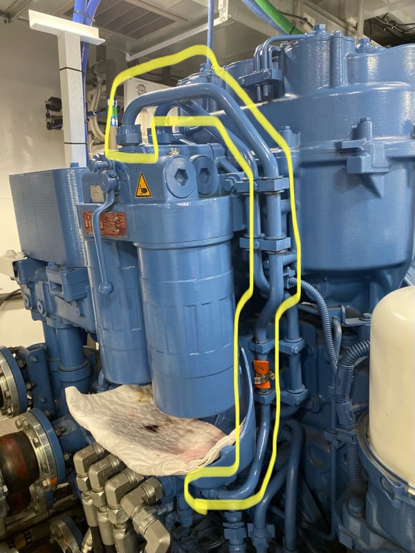
Also, would adding ban accumulator to the line be a solution?
 
Replies continue below

Recommended for you

Can't help with your materials, but adding an accumulator would likely help. There's nothing worse than vertical up flow in any suction line.

 
This particular line is being fed by a gear pump and is pressurized to 65 psi. This line supplies a 4 piston reciprocating pump that outputs from 15,000 to 37,000 psi.

It's under warranty and the mfg keeps taking the failed parts so I don't get to investigate. I think a simple accumulator would fix the problem but I'd also like to avoid introducing elastomers. This is a diesel fuel injection system.

Warranty doesn't cover downtime.
 
Flow rate?

Flow up or down on that line?

RPM of the pumps?

Velocity in the pipe?

ID of the pipe.

Where is the erosion taking place on that line? Always in the same place?
I assume that orange thing is the patch.

Remember - More details = better answers
Also: If you get a response it's polite to respond to it.
 
TagboatEng,

Are you able to measure pressure in that suction line during operation? The line may not be under the same 65 psi all the time. The reciprocating pump and the gear pump might not be working together in harmony. In case the pressure drop under the atmospheric pressure during suction of the reciprocating pump it may cause pitting corrosion with the knocking noise. Stainless steel has more resistance to pitting corrosion.

Additionally reciprocating pumps should have accumulator in the suction line, as well as on the discharge line to stop pulsation and mechanical vibrations.
 
This is a common rail fuel injection pump on a diesel engine. The gear pump and piston pump are driven together on the same shaft. The tube buzzes loudly, it's almost as loud as the engine. Originally, the fuel pressure transducer was giving a fluctuating reading so the manufacturer replaced a section of the tubing with PTFE hose. Now the fuel pressure reads constant but the buzzing and erosion continue. The line fails after about 1000 hours of operation.
 
How about some data?

You must know how much diesel this thing uses?

Remember - More details = better answers
Also: If you get a response it's polite to respond to it.
 
Sorry, I'll provide what I can.

Tubing ~19mm and should have ~1.5mm wall thickness.

The fuel rate through this line should be close to the consumption of the engine which is 150 gph. The relief valve for the supply pump is before this line so it shouldn't see full supply pump volume.

The line in question supplies the pump #1 in the image but is not actually pictured.

Screenshot_20210704-114510_sngcta.png


Each injector has an accumulator on it so the high pressure side seems to be well damped.

I am not sure how rail pressure is regulated on this system. Other manufactures' systems use valves to time the start and stop point of each plunger's pump cycle. I think this system has a single inlet control valve. The buzzing starts once rail pressure is established so I know it's tied closely to that valve.

This engine is a new family and one of the girls follow units. It's also under warranty. The manufacturer is working on a solution but until then is replacing the line regularly. However, we have had a failure within the replacement window and the risk associated with atomized fuel spraying in to an engine room is unacceptable. I'm just looking for some ideas I can bounce off the manufacturer because it's been over a year and they haven't moved meaningfully towards a solution.
 
TugboatEng,

Is the gear pump relief valve too wide open that the inlet line is seeing less pressure and higher velocity to give you low pressure cavitation and erosion? Did you play with the relief valve setting and see how the inlet line and the reciprocating pumps react? I have a feeling that the railcar backpressure, the reciprocating pumps relief valve setting and the gear pump relief valve settings are not synchronized.

Check what is the:
Railcar back pressure?
What's the reciprocating pumps relief valve setting? Where is the relief going? Is it directly being added to the suction line or though a tank? If tank, what's the pressure?

All we know that the feed pump(gear pump) outlet is starving and causing the cavitation/erosion.

The other option could be to increase the inlet line size, which could be a little tedious.

GDD
Canada
 
GD2, the gear pump relief is fixed and returns to tank. There is no relief in the piston pump but its outlet pressure varies from 15,000-40,000 psi. The gear pump capacity exceeds the piston pump capacity at all times.

Increasing the line size is a possibility.

Hose is challenging as it should meet rules set out by classification societies.

I think the cavitation is a result shockwaves from the control valve on the inlet of the high pressure piston pump.
 
If I was faced with this and not allowed to change flow related issues I would go with a larger line and use 2205 duplex stainless for it. It is a workaround for sure, sounds like they have a systems issue.

= = = = = = = = = = = = = = = = = = = =
P.E. Metallurgy, consulting work welcomed
 
It does seem to be a fairly small line and piston pumps do strange things, but I'm still struggling to see how with that much pressure you're seeing erosion / cavitation type damage.

But strange waves sometimes appear so a bigger line and hardened steel would be a good bet to start with until you can add an accumulator.

Are those duplex fuel filters?

Do they block or clog frequently?

Could you add a tee to that line and then measure fuel pressure right at the pump inlet? If you put a transducer on it you might be able to pick up the pressure waves / fluctuations from the pump.


Remember - More details = better answers
Also: If you get a response it's polite to respond to it.
 
Just thinking out loud here, what's causing the cavitation, assuming it is cavitation - cavitation is the vapourisation of a fluid going back into solution in an area of higher pressure. Is this happening in your case and what's causing it? I can only imagine the fuel being rapidly accelerated to cause a local low pressure area and then going back into solution further along the pipe - is this possible?

It is a capital mistake to theorise before one has data. Insensibly one begins to twist facts to suit theories, instead of theories to suit facts. (Sherlock Holmes - A Scandal in Bohemia.)
 
I will look in to measuring frequency.

Artisi, I do believe the cavitation is caused by rapid accelerations.

I need to correct the operating pressure number. This line is at 150 psi, not 65 (that's for a different engine).

The manufacturer is replacing both the inlet and outlet lines from that filter. I don't know that the wear is equal in both lines, they immediately get sent back to factory.

In the image is the final of 3 duplex filters, one drawn through two pushed through. We have not experienced clogging, this vessel operates with a centrifuge. I imagine metal from failing lines is getting in to the high pressure pump.

I will provide a more accurate sketch of the system when the vessel is available.
 
Status
Not open for further replies.
Back
Top