-
1
- #1
thread507-459248
I got a little sidetracked into this thread.... I was actually scanning to see if anybody mentioned the Zuraski paper in that discussion (Zuraski, discussion of Cb from Engineering Journal. I didn't find it. Oh, well. I think I read it years ago, but don't seem to have a paper copy of it laying about (or it's not listed in my inventory...).
Not sure why this got labeled as a "rafter" since it looks like everything is structural steel and it all looks flat with metal deck, but that's not where I'm going with it. A lot of posts on this site start out with some really odd title and you've got no real idea what it's about, just saying. Just thought I'd mention that. I think there's a lot of "standard" terminology that's not actually standard.. To me it's a beam, not a rafter and "fly brace" is a new term to me as of today.
While I didn't read the whole thread (let alone read and understand it/replicate it), one thing did seem worthy of mention and I didn't see it mentioned in that thread.
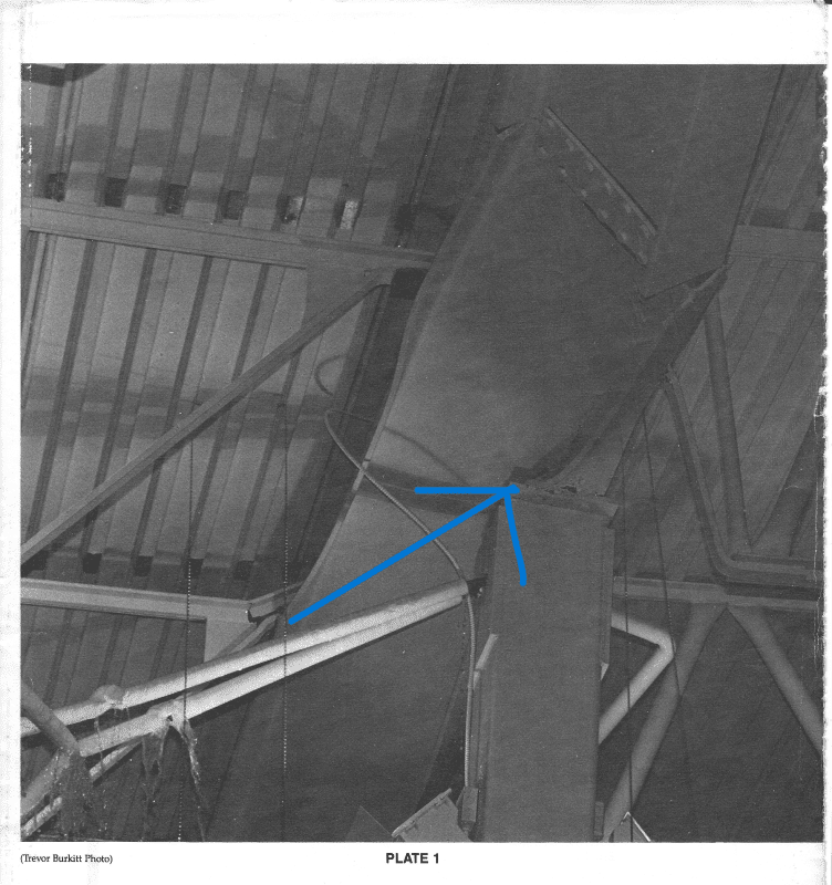
It's this picture, where the beam above a column has buckled. This is a stability issue (of course), and it was discussed at a Stability seminar from AISC I remember going to way back when.
As a side note, "Steel Design After College" (on youtube and with a PDF), Link coincidentally has a fair bit of coverage on Cb that is worth watching/reading, particularly for uplift, and less-so for things like "cantilever roof framing" or Gerber Girders, etc. (they're about same thing, Gerber is an older / Canadian name for it from what I've seen.
Anyway.

You're supposed to put a web stiffener here. from the look of the deflected shape, this is inelastic buckling due to compression on the bottom flange of at the column. While the text in the original post stated the joists are 'normally considered as brace points' (that's perhaps true from a how people designed things back in the day), it's untrue to reality, as the beam looks like the bottom flange was in compression, for this to count as a brace point, the bottom flange can't be in compression, so the analysis is using a brace where there really isn't one. It is similar to the "inflection point considered as a brace" that has since been highly discouraged. Keep in mind there are still structures out there that may use this design approach and be aware of them, particularly when looking at cantilever beam framing systems.
Regards,
Brian
I got a little sidetracked into this thread.... I was actually scanning to see if anybody mentioned the Zuraski paper in that discussion (Zuraski, discussion of Cb from Engineering Journal. I didn't find it. Oh, well. I think I read it years ago, but don't seem to have a paper copy of it laying about (or it's not listed in my inventory...).
Not sure why this got labeled as a "rafter" since it looks like everything is structural steel and it all looks flat with metal deck, but that's not where I'm going with it. A lot of posts on this site start out with some really odd title and you've got no real idea what it's about, just saying. Just thought I'd mention that. I think there's a lot of "standard" terminology that's not actually standard.. To me it's a beam, not a rafter and "fly brace" is a new term to me as of today.
While I didn't read the whole thread (let alone read and understand it/replicate it), one thing did seem worthy of mention and I didn't see it mentioned in that thread.
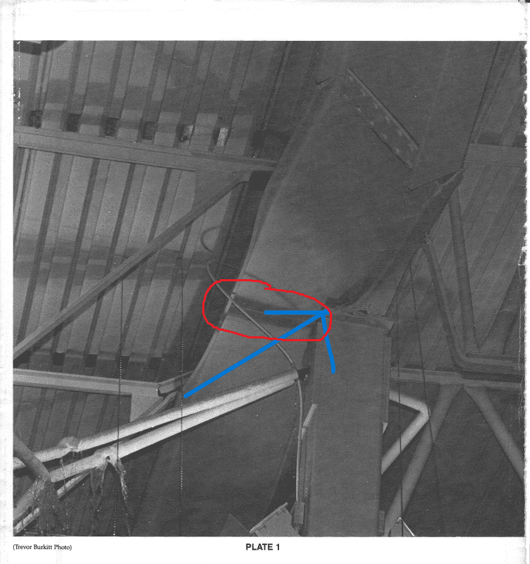
It's this picture, where the beam above a column has buckled. This is a stability issue (of course), and it was discussed at a Stability seminar from AISC I remember going to way back when.
As a side note, "Steel Design After College" (on youtube and with a PDF), Link coincidentally has a fair bit of coverage on Cb that is worth watching/reading, particularly for uplift, and less-so for things like "cantilever roof framing" or Gerber Girders, etc. (they're about same thing, Gerber is an older / Canadian name for it from what I've seen.
Anyway.

You're supposed to put a web stiffener here. from the look of the deflected shape, this is inelastic buckling due to compression on the bottom flange of at the column. While the text in the original post stated the joists are 'normally considered as brace points' (that's perhaps true from a how people designed things back in the day), it's untrue to reality, as the beam looks like the bottom flange was in compression, for this to count as a brace point, the bottom flange can't be in compression, so the analysis is using a brace where there really isn't one. It is similar to the "inflection point considered as a brace" that has since been highly discouraged. Keep in mind there are still structures out there that may use this design approach and be aware of them, particularly when looking at cantilever beam framing systems.
Regards,
Brian

