Eng-Tips is the largest engineering community on the Internet

Intelligent Work Forums for Engineering Professionals

  • Congratulations waross on being selected by the Eng-Tips community for having the most helpful posts in the forums last week. Way to Go!

CBUSH coincident nodes

Status
Not open for further replies.

alphamax

Aerospace
Sep 1, 2015
1
AT
CBUSH or CELAS elements are often used with two coincident nodes.

But how is this possible, as the stiffness values are of the unit N/mm?
I do not understand how there can be a stiffness applied, when the spring has a length of 0.

Thanks for your answers in advance!

 
Replies continue below

Recommended for you

Dear Alphamax,
CBUSH is a structural scalar element connecting two noncoincident grid points, or two coincident grid points, or one grid point with an associated PBUSH entry. This combination is valid for any structural solution sequence. The use of CBUSH element has all advantages over CELASi elements. For example, if you use CELASi elements and the geometry isn’t aligned properly, internal constraints may be induced. The CBUSH element contains all the features of the CELASi elements plus it avoids the internal constraint problem.

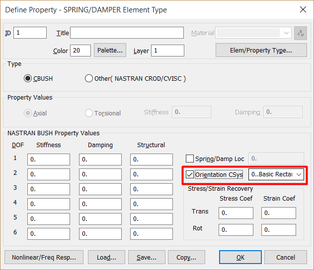
The Orientation CSys option defines the CBUSH element coordinate system for the element referencing this property, allowing to use two coincident grid points for the element definition. If the Orientation CSys option is off, then Nastran will determine the element coordinate system from the orientation defined on the element.

cbush-props_bebwor.png


Best regards,
Blas.

~~~~~~~~~~~~~~~~~~~~~~
Blas Molero Hidalgo
Ingeniero Industrial
Director

IBERISA
48004 BILBAO (SPAIN)
WEB: Blog de FEMAP & NX Nastran:
 
Hi,
I have a question regarding CBUSH on non-coincident grid points.
The Nastran QRG states that:

The CBUSH element is designed to satisfy rigid body equilibrium requirements. For
noncoincident grids, internal rigid links connect the bush location to the grid locations. This results in coupling between translational and rotational degrees-of-freedom at the grids even when no rotational springs or dampers are specified on the PBUSH.


What is the exact effect on the model? I looked at the ELFORCE for the CBUSH elements after running a static analysis (SOL101) and I see only axial and shear forces and infact my PBUSH card was as follows

PBUSH, 1 , K , 1.+10 , 1.+10 , 1.+10 , 1. , 1. , 1.

So what is the coupling of which the QRG is talking about?

Thank you
Regards
 
Status
Not open for further replies.

Part and Inventory Search

Sponsor

Back
Top