Continue to Site

Eng-Tips is the largest engineering community on the Internet

Intelligent Work Forums for Engineering Professionals

  • Congratulations cowski on being selected by the Eng-Tips community for having the most helpful posts in the forums last week. Way to Go!

CDEGS - Current Flowing - Plotting

Status
Not open for further replies.

FouNation

Electrical
Jul 20, 2023
3
How could I plot current flowing in a conductor, with x-axis being the distance from the origin of the conductor and the y-axis being the value of current flowing at this segment ? I am using CDEGS HIFREQ in order to design cables
 
Replies continue below

Recommended for you

Kirchhoff would probably plot that as a straight line.
However if conductor was losing current due to low resistance (poor quality cable or an intentionally conductive matrix as used in some heating cables) or capacitive losses the plot will be a sloped line.
Current flow creates a voltage drop.
If the voltage drop is enough to affect the losses, you will have a curve.

--------------------
Ohm's law
Not just a good idea;
It's the LAW!
 
I was going to say something line current in = current out with possible time delay, until I looked at the program description. Now I am fairly sure I do not understand the contest of the question enough to offer suggestions.
[URL unfurl="true" said:
https://www.sestech.com/en/Product/Module/HIFREQ[/URL]]
Screenshot_from_2023-07-22_05-39-55_wrrceb.png

Technical Description
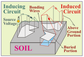
HIFREQ is an optimal computation tool for tackling complex electromagnetic problems involving any system of conductors, which can be comprised of various materials and assembled in various configurations, and which may include metallic plates, coaxial or multi-core cables, GIS/GIL, transformers, and assorted lumped components (e.g. resistors, inductors, and capacitors, etc.). HIFREQ is the only computation module that can provide accurate solutions to transient and steady state problems in the frequency range of zero to hundreds of megahertz, for the analysis of buried and aboveground conductors. It computes electric and magnetic fields in the air and soil, as well as conductor and soil potentials, and the current distribution in the soil and in the conductors.
 
Where the current flows is a function of the frequency of the current being applied. Up to a point, it looks more or less like a constant ratio across the whole diameter - barring little eccentricities like multiple stranding and associated "pockets". However, at higher frequencies it will appear at thinner and thinner "shells" related to the maximum cable diameter (i.e., the last few strands near the insulating jacket). If the frequency is high enough, no current will flow because the cable will look like an open circuit.

This is why the ground cables for variable frequency drives are recommended to be so large - at typical semiconductor switching frequencies (which are only a few thousand hertz) it isn't a function of the cross-section any more - it's a function of surface area.

Converting energy to motion for more than half a century
 
Status
Not open for further replies.

Part and Inventory Search

Sponsor