Continue to Site

Eng-Tips is the largest engineering community on the Internet

Intelligent Work Forums for Engineering Professionals

  • Congratulations GregLocock on being selected by the Eng-Tips community for having the most helpful posts in the forums last week. Way to Go!

Cenrrifigal By passline 70%, 30% to process 1

Status
Not open for further replies.

bmw318be

Mechanical
Jun 16, 2010
197
Hi,
I am sizing the pump that is already the smallest

Total head requuired is 20 m,
flow 7 m3ph

The smallest pump is having
25 m3ph 20 m.
Throttled to 30 m , Would get 7 m3ph,this the recommended throttled to get

Can we throttled to 30 m, then the balance of liquid like 4.5 m3ph going to the retun bypass line and 2.5 m3ph to the process.

May i clarify.
1. Shall the recirculation line same size as process line ?

2. What is the recommended valve to be installed in process and bypass line ?

3. How to know how much flow passing the process and circulation line ?
 
Replies continue below

Recommended for you

Globe valve, one for each branch. Recirc and process lines do not need to be the same size.

I used to count sand. Now I don't count at all.
 
Even the pump is fine for the required flow-head as specified, it may be operated not at the best efficiency due to the low flow operation for a large pump.
 
How to know how much flow passing the process and circulation line ?
Woule varies the head on the process, changing the flow to the bypass and vice versa ?
 
For the process flow requiements, you may add flow control valves on both process and bypass line and a meter on the process line to achieve it. If needed, a Instrument/Control Engineer can help you with the required instrumentation system based on the process operation.
 
Mk3223,

Thanks, can you elaborate in general, Let say having 8000 LPH at 31 meter head.

If I would like to have going to process only 30% and 70% going to the bypass lines.

How many % process valve need to close and % bypass lines need to close ?
 
The conditions specified above is too simple, and it can be resolved with many answers. Let's try it,

1. If the process and bypass lines are the same size and pressure head conditions, the percentage of the valves opening can be the same as the flow rate percentages, i.e. XX% open for XX% flow.

2. If both lines size not the same, the actual flow through each line may be balanced by the valve opening and pressure head to achieve the flow as specified.

3. Based on the above conditions, you may record the flow and open % on an Excel sheet, and use it for the operation.

4. You may need some instruments to meet the required operation, either a manual control with PI and FI, or an automatic system with PC and FC.

It can be helpful for a better answer if more specific process conditions or system configuration can be shared.


Why would you not just throttle a single line and avoid paying for all the recirc mass-flow? It's not like the pump won't have more than enough flow.

Keith Cress
kcress -
 
Hi mk3223

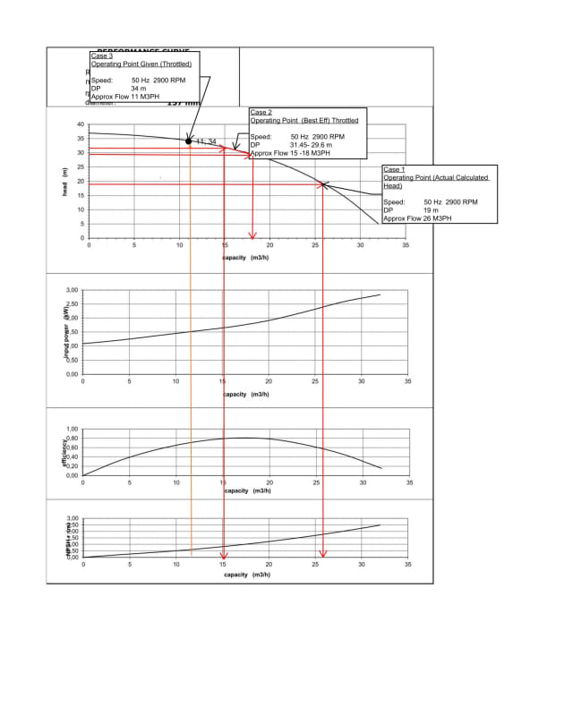
I have advised to run the pump with the performance curve attached near to the BEP-Break Efficiency Point.Which would cause some of the flow to be by pass in some cases to the tank.

The BEP is at 15 M3PH, according to the curve, the head required is 31.45 m.

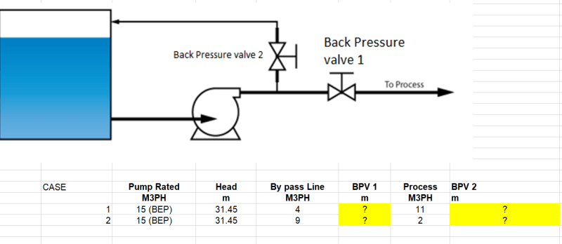
Now as suggested, install the back pressure valve or regulating valve at process and by pass line. Understand if installed at process line, it would be easy to simulate the flow and pressure, however now we have 2 lines (By pass and Process), How many % of the valve to achieve my desired cases below.

Assuming that i am using 1.5" inches pipe, what would be the back pressure valve for my case 1 and 2 ?.

The case [attach
15_M3PH_31.45_BEP_dz7byb.png
ed]


Performance curve [Attached]
PERFORMANCE_CURVE_CENTRIFUGAL_PUMP_dr1rgv.jpg
 
BEP is Best Efficiency Point.

Running close to that makes sense if all the flow is going forward.

As soon as you throttle some of it back to the tank you're essentially wasting energy.

You would probably use less energy at 11m 3/hr if you just throttled it.

To use a pump to flow 2m3/hr when it's designed to operate at around 20 makes no sense.

Your OP said "I am sizing the pump that is already the smallest" Now it might be the smallest from that particular Vendor, but smaller pumps exists.

Your control system won't work on pressure. It needs to link flow to the bypass line control.

Remember - More details = better answers
Also: If you get a response it's polite to respond to it.
 
I agree, it makes no sense to force the pump to operate at it's BEP by wasting energy recirculating liquid. Just look at the curve you posted, case 3 uses less power compared to case 2, even though the pump is less efficient at that operating point.

Have you looked at reducing the pump speed with a VFD?
 
I would need the head of 20 m, having use VFD would reduce the head too.

The motor is small power and case 1 is not often run.

What do you suggest the throttle at process and bypass in orser to get the floe ratio ?
 
Small pumps can be run far to the left side of the head vs flow curve for long periods without damage.

External recirculation is a good idea if you will be running at flows which are a small fraction of the BEP flow. It gives you one more knob to turn, in addition to a discharge throttling valve, to help the pump operate at a stable non-surging operating point. It also helps dissipate heat which builds up due to inefficient operation of the pump.

You could likely run that pump down to 5 m3/hr with throttling without any external recirculation. It would waste some energy, but not enough to justify bothering with a VFD. And you certainly don't need either external recirc or a VFD to operate permanently at your case 3 (15 m3/hr)
 
bmw318be - So? Your pump is capable of more than 20m of head. Don't blindly run at BEP when recirculating and assume that makes the system the most efficient. You need consider the efficiency of the WHOLE system once you start purposely wasting power/energy.

As for the valve % - they need to be whatever is required to produce the results you want. In the real world, this likely means some kind of automatic process control system to control the recirculation flow as the process demands change.

moltenmetal - If you look at the posts, he maybe wants to run down to 2m3/hr or 2.5m3/hr. It's not really clear. I'd agree that simple throttling would definitely make the pump less efficient, but the pump efficiency loss has to be compared to the whole system efficiency if making the pump more efficient by wasting energy using a recirculating loop.
 
At 2-2.5 m3/hr, external recirculation would be recommended to avoid problems associated with running the pump too far to the left of its curve. It may run fine, but it may surge quite a bit and unstable operation is hard on even small-ish pumps like this.

Efficiency at this scale is going to be tough to achieve with a centrifugal. Reducing speed with a VFD won't help if you need the head. Nobody makes a 6" impeller (needed to develop the required head) which is only 1/8" thick (which is all you'd need to develop the required flow) and if they did, that too would be inefficient.
 
bmw318be, it's a good spread sheet to start.
If doing the calculation manually, you can calculate the hydraulic heads at the downstream of the valves BPV1 and 2 per pip size & length, flow rates, etc. And then, you need to know the BPV valves Cv for calculating the opening percentage.
As mentioned above, the instrument control system can be added to facilitate the operation.
 
Also recognise pump flow changes with level and pressure variations in source vessel, if you run the pump at constant pressure at the discharge end.
 
Status
Not open for further replies.

Part and Inventory Search

Sponsor