Eng-Tips is the largest engineering community on the Internet

Intelligent Work Forums for Engineering Professionals

  • Congratulations waross on being selected by the Tek-Tips community for having the most helpful posts in the forums last week. Way to Go!

Center of rigidity

Status
Not open for further replies.

JoanWill

Structural
Oct 4, 2019
15
0
0
MX
Hi guys,
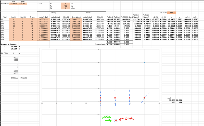
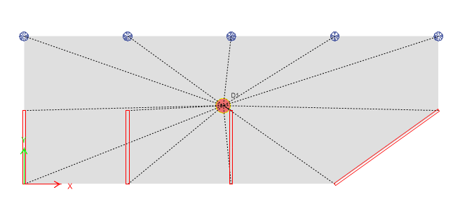
I have a 10m x 28m floor plate that is 200mm thick, supported by four 5m-long walls spaced at 7m intervals. The last wall is oriented at a 45-degree angle to the global X-axis.
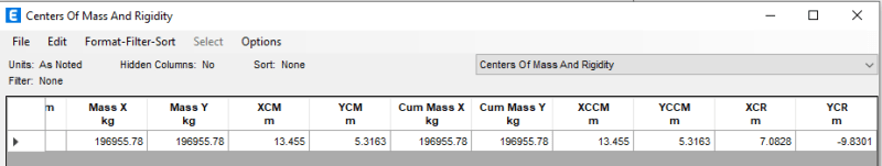
I obtained the center of rigidity (COR) values from ETABS, and the negative YCR value is causing confusion. (when I remove the last wall positioned at a 45-degree angle to the global X-axis, the YCR becomes positive, which makes more sense).

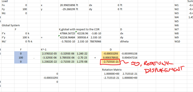
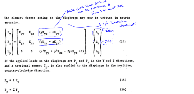
Calculating the center of rigidity manually for orthogonal walls doesn't pose any issues for me. However, I'm struggling to determine the COR when dealing with non-orthogonal walls. Although I've used the same approach as I did for orthogonal walls, my calculated YCR is positive, unlike ETABS' results. If anyone could shed light on why this is happening and wouldn't mind sharing how to accurately calculate the COR in this scenario, I would greatly appreciate it.

PLAN_kggxwh.png


CR_prvdty.png
 
Replies continue below

Recommended for you

I would calculate the Ix and Iy of the sloped components. You can modify your spreadsheet to include an angle, with a default of 0 rotation.

-----*****-----
So strange to see the singularity approaching while the entire planet is rapidly turning into a hellscape. -John Coates

-Dik
 
My spreadsheets take an input of dimension x, and y. I've not had an opportunity to have a sloped (in plan) 'shear wall'. For single elements you could calculate the equivalent x, and y dimension that gives you the equivalent Ix and Iy. As a caution the transformed dimensions will not likely give you the same area, and allowances should be made for this.

-----*****-----
So strange to see the singularity approaching while the entire planet is rapidly turning into a hellscape. -John Coates

-Dik
 
Even if you take the resultant moment of inertia though, the center of rigidity shouldn't be a negative y-value. That's physically impossible. It should be squarely in the middle of the sloped shear wall in the y-direction. This is definitely an ETABS modeling issue.

Things to try, though some are long shots:
-Check your slab analysis mesh and make sure everything is connected.
-Try assigning an auto rectangular mesh to the shear walls. Angled slabs sometimes does weird things to the analysis model.
-It might not help, but draw the shear wall in the opposite direction (for example, draw it right to left instead of left to right).
-Check the shear wall material and wall definitions to make sure there are no weird modifiers; set everything to 1.0 for testing purposes, even out-of-plane moments.
-Check column and slab stiffness modifiers for any weirdness.
-Make sure slab material is orthotropic (or whatever the word is for equal stress/strain in all directions).
-Check that seismic mass is defined correctly, with the correct load patterns.
-Check weirdness in P-delta and nonlinear analysis settings (though this shouldn't affect rigidity calculations, but it doesn't hurt to check).
-Check if you're using a non-rigid diaphragm.

If all else fails, maybe just hand calculate what forces the shear walls should take in an ideal situation with the Iy, Ix, and torsion components. Apply a test load and see if the shears in the walls match what you expected. If it matches, then maybe the model is fine after all. I've done this before and I've confirmed that ETABS will distribute loads in a rigid diaphragm similar to hand calculations.
 
Refer to this thread for a stiffness matrix method: Link

Since you essentially only have 1 element that directly resists loading applied in the global X direction your lateral system is reliant on twist to engage all the walls in the Y direction to counter the Y force component generated by the resistance of the sloped wall a coincident point for the elements ends up in the negative Y.
 
Thank you all.

@dik. I do have consider local stiffness and convert to global one for non-orthogonal walls. I am just not getting the negative YCR. Not sure where I did "wrong".

@milkshakelake, I have checked the model many times and I don't find anything wrong with it. Like I said, the "problem" comes from the angled wall. When I remove it the YCR is positive. I have changed the wall direction but the result is the same.

@Celt83, I think we are using similar method. Does this non-orthogonal wall work ok for you?

 
Yes, the non-orthogonal wall works on my end. Non-orthogonal walls is actually the topic that led me to derive the method. The thread I linked to also contains a link to a spreadsheet I developed, it utilizes US customary units but it shouldn't be to difficult to modify for metric.

 
Thank you Celt83.
It seems that the negative YCR in ETABS is correct then. I will have a look and see what I did wrong in my hand calc.
May I ask which text is this snapshot from?
Capture_ajqbe7_b8rzwq.png
 
Status
Not open for further replies.
Back
Top