Continue to Site

Eng-Tips is the largest engineering community on the Internet

Intelligent Work Forums for Engineering Professionals

  • Congratulations IDS on being selected by the Eng-Tips community for having the most helpful posts in the forums last week. Way to Go!

Centrifugal compressor primary seal gas auto changeover logic 1

Status
Not open for further replies.

amar122amar

Chemical
Jun 12, 2008
65
In our single stage centrifugal compressor primary seal gas is ethylene. N2 is provided as backup in case C2 pressure drops due to any reason. What is the safe logic for seal changeover from C2 to N2? Primary Seal gas flow control valve and flow transmitter is in vendor package. There are individual on/off valves in C2 and N2 supply lines, these are in client's scope. Differential pressure transmitter is available across N2 supply on/off valve.
 
Replies continue below

Recommended for you

i'm not sure about logic.
typically, a check valve is installed in the N2 pipe/tube with ethylene at the higher pressure setpoint. when primary gas is too low, the nitrogen flows into the primary seal system. the nitrogen pressure setpoint will be a little lower than ethylene pressure setpoint. have the vendor furnish an external connection for the nitrogen.
 
There isnt enough information here to get a picture of what the system looks like now
a)Are there design pressure incompatibilities between N2 and C2=?
b)What is the max and min operating pressure range for these 2 supplies
c)Is N2 supply pressure sufficently higher than compressor settleout pressure?
d)Post a P&I D type sketch of these 2 supplies with some details on what is installed on the supply regulation / buffer volumes
e)Typically there is an FSLL on the seal gas flow; in this case, is there an FSHH also?


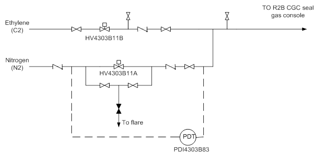
image002_c0a6u4.png


I have attached the drawing of C2 and N2 seal gas supply system. In the seal gas console there is on flow control valve in the common line. This flow control valve controls a fixed flow to compressor seal.

Supply pressure of N2 is 42 barg, C2 40 barg. Compressor inside pressure is 16-20 barg.

The current logic of seal changeover is on differential pressure (PDT shown in drawing). On low value of PDT seal changeover takes place from C2 to N2. For this HV in N2 line opens and in C2 line closes.
 
Think you mean the changeover from C2= to N2 supply happens on HIGH diff pressure?
What about information requested in a, b, c and e -also there is no information provided on upstream supply details requested in (d)

What exactly is the concern here ?

I can see a safety concern : the PDT is a controls systems PDT, and may not be viewed as a safety PDT. Hence another PDT may be required in parallel with this to act as a safeguard i.e. to prevent HV4303B11A from opening when diff pressure is LOW (ie when C2= supply is normal). Pls confirm that this HV is a fail close valve.

Switching back to C2= supply should be manual-remote or from local, and not automated.
 
In auto mode seal changeover takes place from c2 to n2 on low pdi value. This is wrong and needs to be corrected.giving seal changeover logic on high pdi value, converting pdt into PT at downstream of HV in the common line and providing logic on low pressure, providing logic on low flow of seal gas ( FT is in vendor package). These are some of possible solutions but what is the best which is practiced in industry.
a) No design pressure incompatibility between N2 and C2.
b) C2 and N2 supply pressure range 43 to 39 barg.
c) Compressor settle out pressure is 16 to 20 barg.
e) there is an FT in compressor vendor package. Compressor will trip on low low value of flow.
 
One detail still remains unclear: Is there sufficient buffer in the C2= supply side that will cause the pressure to decay slowly on supply failure ; so that there is adequate time to allow for this switchover?
If there is inadequate buffer volume,C2= pressure will drop faster than the switchover will allow, and the subsequent FSLL will trip the cracked gas compressor.

The change over logic based on low pressure is good provided there is adequate buffer on the C2= supply side. Though I've not come across these change over facilities on seal gas supply, dont think it is necessary to enable changeover based on flow, given that low pressure changeover is enabled, which should be reliable enough. If there is low flow, it can only be due to seal gas FIC - FCV failure.

Actually, given that low pressure changeover is implemented, dont see the need for high diff press based changeover. In fact, the PDT should be used as a safeguard against the HV4303B11A from opening when diff press is low - this is to enable an instrumented safeguard - to prevent backflow of C2= into N2. And an RO should be installed in this N2 supply line within the tap points for the PDT to make this loop work. The RO should be sized adequately to create a detectable dp for the seal gas flow. Else install a needle valve and lock it in position.

Hence the PSL triggers the N2 supply flow and closes the C2= line a few seconds later;
the low diff press across the RO closes the N2 supply when dp across the RO is low - this trip loop is to be active only when the N2 supply HV is already open for more than 5seconds say.
 
Thanks for the comments George. It will help. C2 supply buffer will be only volume available from battery limit to compressor console. Exact calcs has to be done.
 
Status
Not open for further replies.

Part and Inventory Search

Sponsor