Continue to Site

Eng-Tips is the largest engineering community on the Internet

Intelligent Work Forums for Engineering Professionals

  • Congratulations IDS on being selected by the Eng-Tips community for having the most helpful posts in the forums last week. Way to Go!

Centroid of "tension reinforcement" in beams 2

Status
Not open for further replies.

Lomarandil

Structural
Jun 10, 2014
1,897
Alright, have been thinking about this a bit lately, and haven't found any definitive answer. I have an engineering judgement answer in mind, but I'd love to see if it's explicitly stated anywhere.

When computing the centroid of tension reinforcement to determine depth of a concrete flexural member (d), what reinforcement is included?

[ul]
[li]bars nearest the tension face[/li]
[li]bars in the "tension half"[/li]
[li]any bar which reaches tension yield[/li]
[li]side face bars in deep beams[/li]
[li]all bars with tensile force (weighted?)[/li]
[/ul]

Bonus question: which of these bars count toward providing minimum flexural steel?

(My context uses lightly reinforced members for economy, and I mostly work using ACI, but am happy to hear how other codes handle it)


----
just call me Lo.
 
Replies continue below

Recommended for you

ACI 318-14:
d - distance from extreme compression fiber to centroid of longitudinal tension reinforcement, in.

by this definition d my interpretation has been that it is the centroid of any piece of longitudinal reinforcement that by a strain compatibility analysis experiences tension, regardless of the magnitude of that tension.

In a past post some other folks made an argument that this should really be the centroid of the tension force, but that's not the way it's worded in ACI.

My Personal Open Source Structural Applications:

Open Source Structural GitHub Group:
 
I feel celt's interpretation is overly penalizing. I'm in the camp that it's to the centroid of the steel I need for flexure. The skin bars that may experience tension don't count in my calculation of d.
 
I think jayrod12 is right. there may be some consideration for different strains.... depending on distance from neutral axis... but assuming a well balanced beam ((2) layers of tension steel), it would be the centroid of tension steel. That said, you dont have to use it all... obviously considering As max, you may just use the steel you need to show an adequate beam design. Torsion, is often overlooked.
 
For flexural strength, technically it is the depth to the centroid of the tension force considering the relative strains over the section depth.

For shear design in some codes (Canadian and Australian) it is the centroid of the area of the steel in the tension half depth. Other codes it is the centroid of the tension steel, which is stupid if you include a bar that is nominally in tension near the neutral axis as its full area with one that is at yield.

When you start to deal with small depths or large covers, quite often the reinforcement at the compression face can be in tension. This tends to give stupid results, especially when combined with shear design rules. So for several years we have ignored bars within about 1/3 of the depth from the compression face, even if they are in tension.
 
Yeah, I have to admit that I didn't expect to have anyone advocating for the unweighted centroid of any bar in tension option. Celt, any background on what brought you to that conclusion?

I am primarily thinking about this for the effect on shear capacity and maximum stirrup spacing. Even taking a centroid of tensile force, I'm still finding d~55%h for some beams, unless I chose to ignore bars as rapt mentions.

----
just call me Lo.
 
I looked into a bit ago and never found anything beyond the definition presented in ACI, which to me says nothing about only bars at yield or below the neutral axis by a certain amount. it says:
"ACI 318-14:
d - distance from extreme compression fiber to centroid of longitudinal tension reinforcement, in."

Reading a bit more finely you can find the section that defines when skin reinforcement is required for relatively deep beams which alludes to the fact that you can either increase flexural capacity by accounting for the skin bars in a strain-compatibility analysis or ignore them. If you ignore them then you get a lower overall flexural strength but then d only needs to be based on the bars in tension from that analysis likely 2 layers at most so you take a small hit to flexural capacity but get a larger shear capacity. Likewise if you did the full strain compatibility analysis you would gain increased flexural capacity but now all of the steel is tension steel so you take a hit on d for shear. So you could rationalize this ignoring of skin bars to cover any set of bars above your "primary" tension steel.

For what it's worth I agree with Rapt, taking the definition for d literally as I have can give you stupid results especially for slabs with drop panels and a continuous bottom mat of reinforcement.

My Personal Open Source Structural Applications:

Open Source Structural GitHub Group:
 
rapt - Canadian code calls it as the centroid of the tension reinforcement, not centroid of reinforcement in tension. Seems fairly clear that you can exclude skin reinforcement for this. There's also the effective shear depth limit of 0.72h, which seems to exclude the case where you're considering skin reinforcement as well.
 
This months issue of Concrete International had an article with some research on the effective depth consideration for columns:
Link

My read of the article they are suggesting that 0.8H or 0.8D, H=Column Depth D=Column Diameter are more appropriate than the current centroid of tension steel definition.

My Personal Open Source Structural Applications:

Open Source Structural GitHub Group:
 
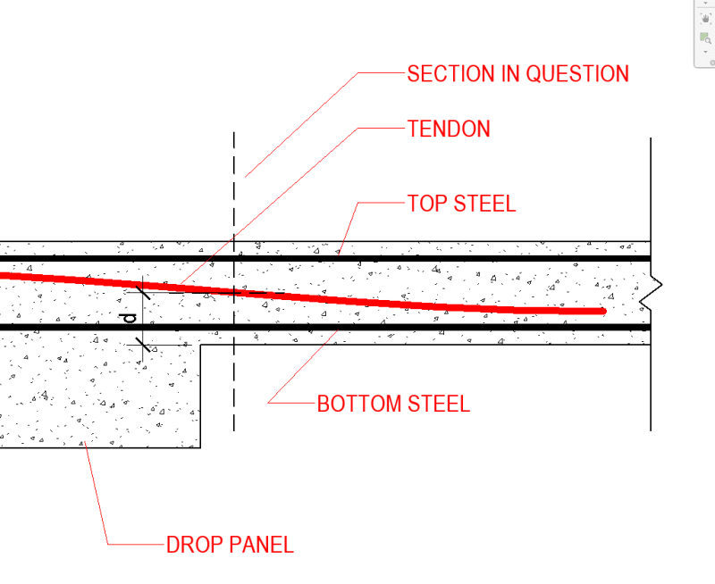
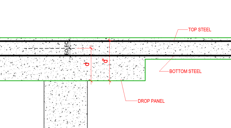
Celt, you are saying that programs like Concept will pick d to be the item labelled as d, not d' below correct? I think concept abides by this "by-the-book definition" of d as well.

Droppanel_qp0diw.png


I was chatting up their technical support on a recent PT drop panel job regarding the determination of d dilemma and received this response:

RAM Concept Tech Support said:
ACI 318 defines the effective depth as "distance from extreme compression fiber to centroid of longitudinal tension reinforcement." For the section in question, the section tension is resolved primarily through the tendon. For the governing envelope, there is negative moment and the tendon is near the bottom of the section (near the compression face). Since the tension is primarily resolved through tendon and the centroid of the tendon is very close to the compression most face, a low effective depth should be expected.

I do not have a ton of PT design experience, seems odd to me to even include the tendon in the determination of the height of d. Maybe a PT expert could explain this to me. When I was running my hand calcs for the shear design, I was taking d to be the distance to the top reinforcing in the section.

I think the section in question was similar to the image shown below.

Droppanel_ortjbw.png


I need to dig in more closely, but maybe all of concepts calculated 'd' values come from where the PT tendon is in the slab.


S&T
 
EDIT:
Scratch that, you have it correctish in your screen cap. Instead of EQ though it will be shifted based on the Area of top or bottom steel. Also of note is it will only be the lower d value if you specified a bottom reinforcing mat since the automated section design would design only the top bars there and the mat would only be present as user specified reinf.

My Personal Open Source Structural Applications:

Open Source Structural GitHub Group:
 
lomarandil said:
I am primarily thinking about this for the effect on shear capacity and maximum stirrup spacing.

Meeeee too! I've been thinking about this on and off for years now. I doubt that I actually have the answer on this one but, at the least, perhaps I can stimulate some interesting discussion. Take everything that follows as being at least part conjecture.

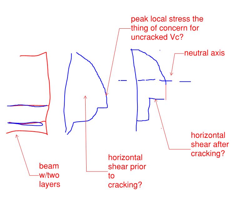
1) In what follows, consider the two sketches of horizontal shear below, across a beam both prior to cracking and after cracking. I've probably screwed up the exact shapes but, hopefully, I've captured the salient features.

2) Vc.... ohhhh Vc. My understanding of Vc is this:

a) Prior to shear cracking cracking, you're trying to prevent the peak, local shear stress from exceeding the value that would initiate cracking. Check.

b) After shear cracking, we assume that the cracked Vc is the SAME as the uncracked Vc. Frankly, I've long been astonished at this. Hopefully I'm either wrong about it or it's been validated through some testing that I don't now about.

3) Based on #1 & #2, it seems rational to me that, for the purpose of calculating Vc_uncracked, which becomes Vc_cracked:

a) The most accurate estimate of the shear depth would be to the centroid of the tension force, including all reinforcement by way of strain compatibility.

b) The most conservative estimate of the shear depth would be to the centroid of the tension reinforcement since this increases your averaged shear stress (Vu/bd). Of course, this reopens the question of whether or not one should include rebar not intended to be flexurally active.

In both cases, I feel that you're looking for an averaged value (Vu/b*dv) that captures the peak shear stress value for the cross section prior to shear cracking.

4) My understanding of the minimum stirrup spacing is that the goal is to have a minimum number of stirrups cross each potential shear crack. This almost suggests that one could use the depth to the extreme tension steel for this purpose. That said, if our shear design methodology is based on the truss model, then each assumed concrete diagonal needs to touch down where there is sufficient flexural tensile capacity to restrain it longitudinally. And the lowest layer of steel cannot, by definition, supply that by itself. So, for stirrup spacing, I feel that the center of tension is again the most theoretically correct answer. All of this is muddied by the fact that your location of peak moment is not simultaneously your location of peak shear. At the end of a simple span beam, I think that one could argue that the shear depth, for the purpose of stirrup spacing, could be based on the flexural steel actually required at that location, not the flexural steel supplied at that location.

5) At the end of the day, we might just have to accept that shear design is rough stuff, particularly the conventional, non-compression fielded theory formulations of shear design. A truly precise definition of the shear depth based on theory is elusive.

C01_qdvzvi.jpg
 
sticksandtriangles said:
I do not have a ton of PT design experience, seems odd to me to even include the tendon in the determination of the height of d.

I would say that the answer to your question is this: In my sketch above, the tension force contributed by the tendons affects the horizontal shear stress diagrams in much the same way as the mild reinforcement does. This gets a bit murkier when one give consideration to the potential for some of the axial prestress to get "bled off" into shear walls and other restraining elements.
 
I've traditionally used the approach of using the centroid of the tension force utilising all reinforcement in tension. This doesn't meet the centroid of tension reinforcement "area" as defined in codes, but it feels more correct in terms of considering the strain distribution and cross section equilibrium.

Regarding using all reinforcement, our NZ code has only this to say for beams:-
image_cokox4.png


For columns it has the following to say which is essentially the same criteria for any section except circular members, why circular members should be treated any differently, I have no idea. But the exact same mechanisms in terms of shear are at play irrespective of the shape I would have thought:-
image_pxms7k.png


These provisions imply all the reinforcement in tension should be used. However, agree with Rapt that this sometimes creates some weird effects, greatly reducing the effective depth when the top reinforcement is in tension, especially with larger covers and small neutral axes depths.

Including all the reinforcement in tension and on an area basis on top of that as opposed to a force basis does in my mind go against the intent of how shear might work. The additional reinforcement at the top of the section that might go into tension contributes very little to the moment capacity, but has a larger than expected effect on shear strength and more importantly shear reinforcement spacing. Unsure if there is any research to backup requiring it one way or the other, but I'd expect based on applying some engineering judgement that only counting the reinforcement in the bottom half of the section like implied for circular columns was a more realistic approach.

Anecdotally, you'd expect reinforcement in tension higher in the section to enhance the aggregate interlock effect with respect to shear and lowering crack widths and increasing (or maintaining) the concrete shear component, but instead we're told it decreases the effective depth.

 
The other thing, with a lower 'd', the development of tension reinforcement is also impacted as moment coverage considered Ld+d from max moment, or 1.3d from point where no longer required for example (may differ in other codes). But you potentially risk affecting your moment coverage with a lower effective depth. I'm sure there is plenty of conservatism in these development rules, but all the same, they are impacted by a potentially artificially lower 'd'.

 
One more funny effect as d reduces due to top bar tension being considered in determining d is that the shear stress checks are typically based on d.

This results in an arbitrary increase in shear stress which just seems fundamentally a bit bizzare. Consider adding a few top bars to a cross section, and under the same shear force, then the shear stress is higher.... Anyone buy into that logic?

 
Regarding Bonus question
I've always worked out a separate d just based on the primary tension reinforcement (1-2 layers at extreme tension face), and used that for determining minimum reinforcement requirements. Not accounting for any side bars or top reinforcement present that might be in tension, then only provide minimum reinforcement as the primary tension reinforcement (again not accounting for say any side bars you might subsequently add).

 
I was going to link to the Concrete International article, but I see that Celt83 beat me to it (post 16 Jul 21 13:53).

The paper's recommendation to use 0.8D seems to me entirely reasonable; quite apart from the experimental evidence given in the paper, if it works for a circular section, why wouldn't it work for a rectangular section?

However it should be noted that this proposal does not comply with the current code, which obviously remains a requirement for any real design work.

I don't do work to ACI 318, so I won't offer any advice on it, but I note that the authors of the paper interpret the current requirements as follows:

"... the effective depth of the member d, defined as “distance from extreme compression fiber to centroid of longitudinal tension reinforcement, in.” While simple in concept, the calculation of d is complicated for columns, because most column members have multiple layers of longitudinal reinforcement and the neutral axis depth (and thus the centroid of the longitudinal tension reinforcement) varies with axial force and moment at a section. As a result, even if all columns in a structure are identical, their effective depths can differ."

Concrete International, July 2021, Effective Depth of Rectangular and Circular Columns for Shear Strength Calculations, by Halil Sezen, Sergio M. Alcocer, and Jack P. Moehle

Doug Jenkins
Interactive Design Services
 
Status
Not open for further replies.

Part and Inventory Search

Sponsor