jaskamakkara
Structural
Hi guys,
I have a beam that is installed already but needs to have the flanges on one side of a 500mm long section of it removed to make room for a pipe. I am using SCIA Engineer FEM package and I would like to check that there are no adverse buckling effects etc from this flange removal.
Firstly I checked it in the 1D frame model by changing the properties of the 500mm long piece of beam to that of the equivalent channel section and this worked fine. However I was worried that the effect on the LTB capacity of the beam wouldn't be accounted for, so I made the beam with 2d elements and did a non-linear analysis, using the buckled shape of the beam as an initial deformation (which SCIA can do for you), taking the absolute value of this deformation as L/250 which EN 1993-1-1 (Table 5.1) gives for a member on buckling curve b. The solver for the analysis uses geometrical non-linearity (2nd order) also. The material is modelled linearly (i.e. elastically). These conditions are hopefully then in accordance with Table C.1 of 1993-1-5 for checking elastic plate buckling resistance.
My problem now is that I'm not completely sure what I should be checking for in the results of the analysis. Is it enough to simply check that the von Mises stresses are below the yield stress of the steel? That would seem to make sense to me since the code check involves factoring the bending capacity down by a reduction factor that is based on imperfections etc, which is effectively what I am doing by modelling the "real" initial deformation and loading the member.
Do I care at all about the actual deformations of the beam in these non-linear analyses? The deflections (although ULS, so I can factor them down) are quite large and although the model converged just fine I don't know if I should be taking them into account... Obviously if the model didn't converge then I know the deflections are out of control but am I otherwise bothered about their absolute values?
Here are some screengrabs from the model, hopefully my explanation made sense! Feel free to ask for more info:
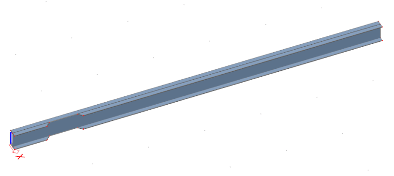
Beam model:

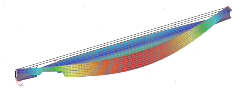
Buckled shape from atability analysis (critical load factor = 1.79 for eigen shape 1):

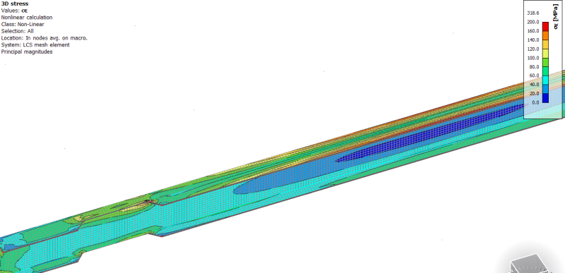
von Mises stresses from non-linear analysis (using ULS loads), here I limited the max stress in the contour diagram to 200MPa so that the concentration at the corner of the flange cut doesn't blow out the rest of the results. In reality these cuts will be radiussed to remove these stress concentrations:

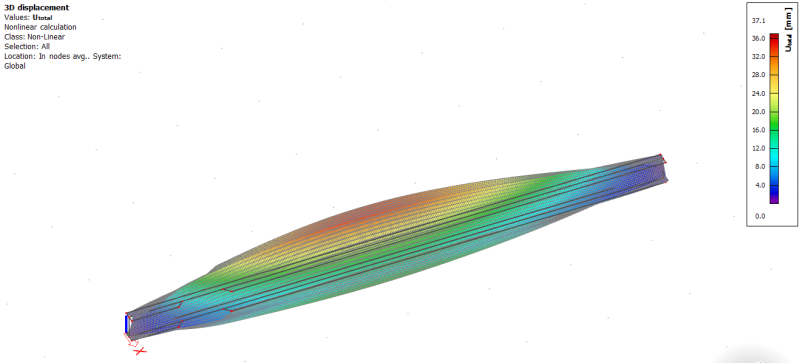
Deflections from non-linear analysis (also using ULS loads):

I have a beam that is installed already but needs to have the flanges on one side of a 500mm long section of it removed to make room for a pipe. I am using SCIA Engineer FEM package and I would like to check that there are no adverse buckling effects etc from this flange removal.
Firstly I checked it in the 1D frame model by changing the properties of the 500mm long piece of beam to that of the equivalent channel section and this worked fine. However I was worried that the effect on the LTB capacity of the beam wouldn't be accounted for, so I made the beam with 2d elements and did a non-linear analysis, using the buckled shape of the beam as an initial deformation (which SCIA can do for you), taking the absolute value of this deformation as L/250 which EN 1993-1-1 (Table 5.1) gives for a member on buckling curve b. The solver for the analysis uses geometrical non-linearity (2nd order) also. The material is modelled linearly (i.e. elastically). These conditions are hopefully then in accordance with Table C.1 of 1993-1-5 for checking elastic plate buckling resistance.
My problem now is that I'm not completely sure what I should be checking for in the results of the analysis. Is it enough to simply check that the von Mises stresses are below the yield stress of the steel? That would seem to make sense to me since the code check involves factoring the bending capacity down by a reduction factor that is based on imperfections etc, which is effectively what I am doing by modelling the "real" initial deformation and loading the member.
Do I care at all about the actual deformations of the beam in these non-linear analyses? The deflections (although ULS, so I can factor them down) are quite large and although the model converged just fine I don't know if I should be taking them into account... Obviously if the model didn't converge then I know the deflections are out of control but am I otherwise bothered about their absolute values?
Here are some screengrabs from the model, hopefully my explanation made sense! Feel free to ask for more info:
Beam model:

Buckled shape from atability analysis (critical load factor = 1.79 for eigen shape 1):

von Mises stresses from non-linear analysis (using ULS loads), here I limited the max stress in the contour diagram to 200MPa so that the concentration at the corner of the flange cut doesn't blow out the rest of the results. In reality these cuts will be radiussed to remove these stress concentrations:

Deflections from non-linear analysis (also using ULS loads):

