structuree
Structural
Hi All,
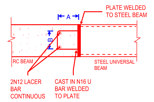
My company commonly uses a similar detail to the below when connecting a steel member to a concrete beam, slab or wall. A 16mm U-bar with 12mm lacer bars to each corner are cast in to the concrete element and welded to a plate. The steel member is then welded to this plate.
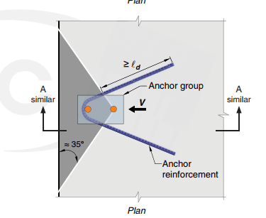
How can I check that the U-bar will not rip out of the slab if there is a large moment applied at the steel beam? I feel like a check of 2 x anchors distance 'B' apart would be overly conservative as the U-bar is continuous and you also have continuous lacer bars to provide an extra layer of defence against pullout. My understanding is that the lacer bars would have to fail in shear and/or the portion of concrete would have to rip out with the U-bar for this connection to fail.
The Australian standards don't seem to provide guidance on checking a similar connection. Could anyone shed light on how I should be checking this or point me in the direction of a resource that covers it?
I am also wanting to understand what governs the 'A' and 'B' dimensions specified on the attached markup. My thoughts are that the 'B' dimension would be governed by minimum bend radius & a greater distance apart is better as you'd have a larger lever arm if you're considering each leg of the U-bar resolves the moment in a push-pull manner, and you'd want the 'A' dimension embedded far enough that it won't be too close to the concrete face that it could pull out.
Any advice, thoughts or links to resources would be much appreciated.


