Continue to Site

Eng-Tips is the largest engineering community on the Internet

Intelligent Work Forums for Engineering Professionals

  • Congratulations MintJulep on being selected by the Eng-Tips community for having the most helpful posts in the forums last week. Way to Go!

Chip Formation in Orthogonal Cutting

Status
Not open for further replies.

VaggelisKas

Industrial
May 11, 2015
36
Hello community,

What element should I use in an orthogonal cutting simulation in order to view the chip formation?
In my simulation I use C3D8R but due to the STATUS parameter in the Field Output Request and the element deletion choice in the element type window
the deformed elements are instantly deleted and no chip is visible.

Any ideas?
 
Replies continue below

Recommended for you

Hello,
I think you can use C3D8R. The cutting edge will really stress elements and they should be deleted instantly (imo). What material model are you using? An input file with the damage definition would be nice to see.

Best regards,
 
Hello,

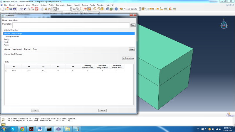
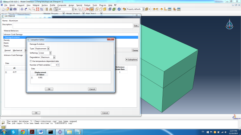
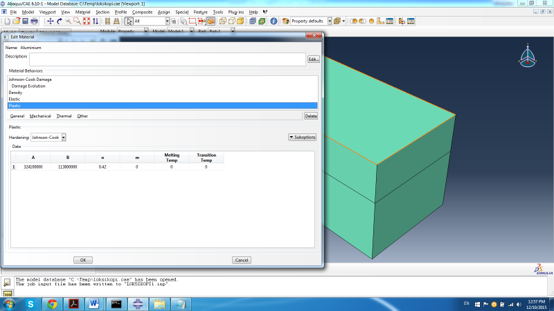
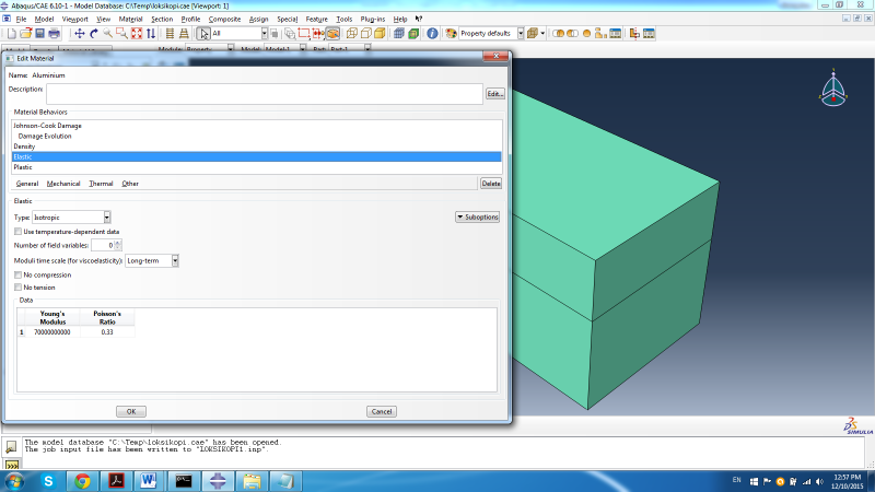
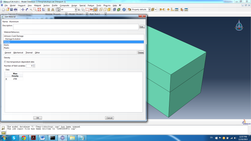
the material specifications (aluminium) I use are the following:
Untitled_eoopaq.png

Untitled1_fvntow.png

Untitled2_eggg47.png

Untitled3_xkz4da.png

Untitled4_olx7uc.png


I also attach the inp file for the above mentioned job.
Link

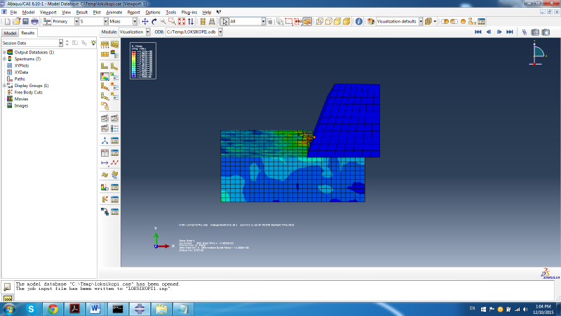
Moreover here is a pic of my simulation and the elements disappearing:
fnj_nlhk7d.png


Thank you for your answer.

Best regards.
 
Hey,
I checked the input file and couldn't find NLGEOM=ON. Check if it is on, otherwise activate it and try again.

I am not familiar with your material model.

If NLGEOM doesn't do the trick, I don't know what is wrong. How confident are you in your plasticity and damage model coefficients?

Good luck.
 
Thank you for your answer.

NLGEOM in the step definition is turned ON.

The material data were taken from a tutorial which has worked for a plethora of other simulations.

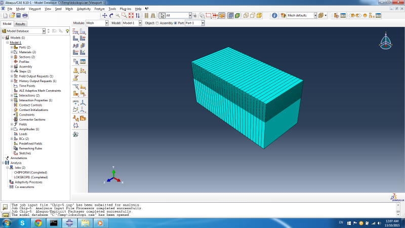
I even changed the seeds of the elements so the final mesh looks like this
Untitled_wpk6kh.png


I also changed the interaction because with this mesh no internal surface needs to be specified.

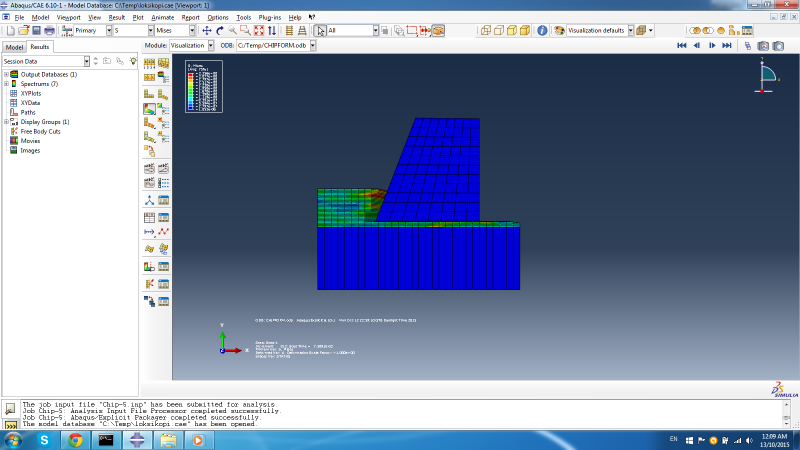
Yet no chip formation can be found and my elements are still being deleted.
Untitled1_b1fdgk.png


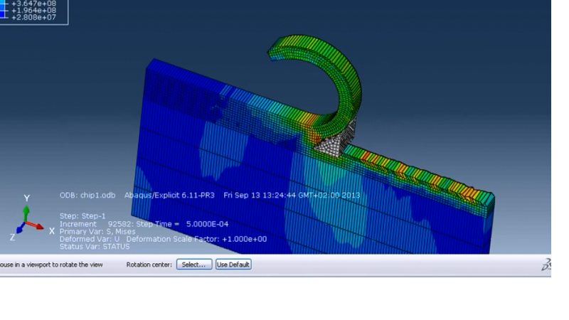
What I want to achieve is something like this
Untitled2_u0lyth.png


Any ideas?

Best regards.
 
Status
Not open for further replies.

Part and Inventory Search

Sponsor