Eng-Tips is the largest engineering community on the Internet

Intelligent Work Forums for Engineering Professionals

Chlorine reaction with refrigerant during Liquefaction 1

Status
Not open for further replies.

Iomcube

Chemical
Dec 11, 2015
181
0
0
TR
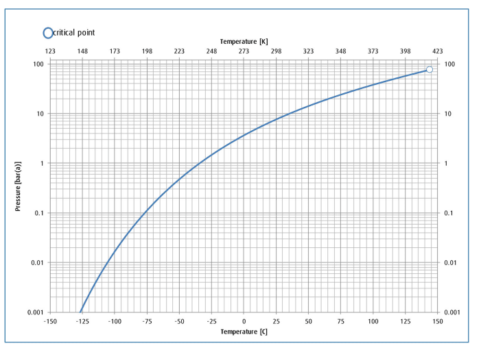
The process of Cl2 liquefaction is detailed here:

1613621885901_kvywbi.jpg


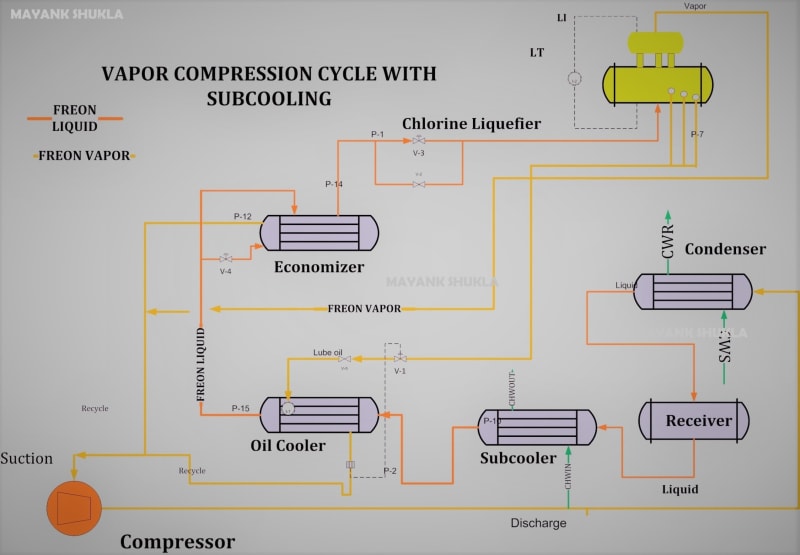
I have seen x2 refrigerants so far being used in Cl2 liquifier R22 & R-509. If the tubular exchanger has some leak ..say the tube side Cl2 oozes out what is the reaction with these refrigerants. I cannot find it.

Secondly...

I know that Cl2 with humidity is enemy of carbon steel thats why we rigorously dry Cl2 (H2SO4 contact towers) before compression / liquefaction. Liquefiers tube / shell side is mostly made of of CS (or very rarely SS). These can be vertical (shell side Cl2 flows via gravity to storage, tube refrigerant) or inclined horizontal (tube side Cl2 flows via gravity to storage, shell refrigerant).


In a new company I have come across this design; tube side is Chilled water (closed circuit with glycol injection) & shell side Cl2. Cl2 pressure is to be higher than water to prevent water ingress into Cl2 (especially liquid Cl2). Do you think its safe or should they be using a refrigerant instead of water (the liquid Cl2 tank made of CS has 12ton cpacity)?

Liquifier_t5hyrx.jpg

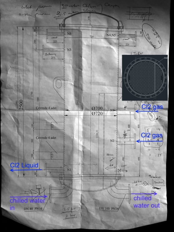
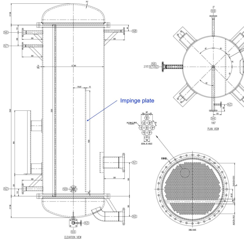
- Common inlet gas header with x2 inlet nozzles to exchanger
- x2 pass exchanger with 75% tubes for 1st pass & 25% tubes for 2nd pass (I dont know the reason)
- In the shell there is an impingement plate before feed Cl2 nozzles
 
Replies continue below

Recommended for you

Strange design
"x2 pass exchanger with 75% tubes for 1st pass & 25% tubes for 2nd pass (I dont know the reason)".
So this cannot be a TEMA U shell

Agreed, Freon would be more inert to chlorine, if chlorine leaked into Freon, assuming freon pressure is lower than that for chlorine.

But Freon is being phased out for some reason or other in modern plants. (I believe it has more to do with UF6 enrichment, from what I read in an article many years ago.) Another alternate to Freon being used these days is R410A.

The risk with ethylene glycol-water mix, is if chlorine leaks into this refrigerant circuit. It would corrode all CS components in the chilled water circuit. How is the chilled water being cooled in this new company?
 
@ georgeverghese (Chemical)
I think this design is for Freon in tube, so 1st pass has lots of volumetric flowrate (saturate gas phase) while the 2nd pass has low volumetric flowrate (liquid freon). So number of tubes for 1st pass are higher

Secondly in new designs Cl2 is pressurised to high pressure say ~5bar ...now we can use simple cooling water to liquify Cl2. Thats why we are using H2O as coolant

Chilled water will be cooled using Trane chiller indirectly in a separate tank circulation circuit

Cl2_curve_kr3jct.png
 
I have been in plants that use water.
The sensors on both sides need to be good, accurate, and very fast responding.
Either water in the Cl or Cl in the water will be a disaster.

= = = = = = = = = = = = = = = = = = = =
P.E. Metallurgy, consulting work welcomed
 
@ EdStainless (Materials)
Thanks for your input. Can you guide me what type of sensors you are referring to? ORP sensors can easily detect Cl2 in water but I am not clear if these work to detect water in liquid Cl2

@ georgeverghese (Chemical)
It is not & you are correct. But what can be the reason of this odd disection of tube bundle?
 
My guess is you have a F shell here - the longitudinal baffle is offset with 25% tubes on one side and 75% tubes on the other side. While the chilled water is a somewhat odd 2 pass setup on the tube side with the same split in the number of tubes (25% on one pass and 75% on the return pass - since I dont see any other pass partition divider on the tube sheet). This may bring up differential thermal expansion concerns if there is a significant operating or design temp difference between the 2 sides.
On the chlorine shell side, the narrower section handles the smaller desuperheating duty, while the wider section provides the larger condensing duty
 
@ georgeverghese (Chemical)
Very helpful comments. I am attaching another design image & its similar. However in the previous design the impinge plate in front of feed Cl2 nozzle is extended all the way down to tubesheet while here there is 30mm clearance. Mind it that Cl2 gas generally has Na2SO4 amounts which in time (5 years lifespan of CS liquifier) foul shell side.

According to you having this clearance is better or not?

001-01_OF_01_Chlorine_liquifactor_-_3-Model_Rev01_2_01_owr8br.jpg

nozzles_v6b4rd.png


I am also attaching heat duty curve (via UNISIM simulation) for Cl2 @3bar 60C ~1.2ton/hr feed to Liquifier (from a compressor). As you can see it changes phase at about 2.5C. From this curve one can observe difference in condensing & sensible duty

KW_cL2_gwzfbw.png
 
What I perceived to be an F shell baffle isnt actually so - this baffle only extends partway up the shell, so I cannot tell what this divider plate is doing. And you have marked it as an impingement plate. But that cannot be the case - the impingement plate is shown immediately next to the N1 nozzle.

The 30mm clearance gap between this divider plate is required: it is meant to allow any chlorine liquid that may have condensed in this desuperheating section to dribble out into the other side of this divider which leads into the N2 liquid chlorine outlet. Without this clearance, the desuperheating section will completely flood up with liquid chlorine.

Ok, from the heat curve, we can see chlorine condensing temp is about 0degC - so shellside operating pressure = 3.5bar abs approx.
 
@ horacio Torres (Chemical)

Nowadays high pressure Cl2 compressors are on market which removes this refrigerant circuit altogether (and we can use Cooling water alone)

However, I agree with you from safety point of view.

Perhaps your inputs regarding liquifier design will be of great importance for me. Also any monitoring instruments that you recommend.
 
Status
Not open for further replies.
Back
Top