Continue to Site

Eng-Tips is the largest engineering community on the Internet

Intelligent Work Forums for Engineering Professionals

  • Congratulations IDS on being selected by the Eng-Tips community for having the most helpful posts in the forums last week. Way to Go!

Chord Force Transfer

Status
Not open for further replies.

structeng2

Structural
Apr 18, 2016
38
Hello,

I have been scratching my head on this for a bit, so thought I would ask.

I've calculated my chord force (CF) in a flexible diaphragm. The metal deck is attached to a perimeter steel beam with puddle welds @12". What is the correct method to determine the force on the puddle welds?

In my opinion, you would follow a similar design to that of shear studs for a composite deck. v = CF / (L/2); where L = length of the chord (in this case, the full length of the diaphragm). I could then directly compare the unit shear demand, v, with my puddle weld capacity @12". Is this correct?

The confusion is coming from another engineer in my office talking about the 'zipper effect', where the highest force is at the center of the diaphragm, which could put a higher load on those welds, causing them to fail and then continue to fail the adjacent welds. I can see what he is talking about, but I don't quite understand how you would calculate that force. I am also confused with this because all the decks I've seen have evenly spaced welds - if this was true, you would have closely spaced welds at the middle with larger spacing towards the ends.

Thanks,
Peter
 
Replies continue below

Recommended for you

To answer your question, it depends on where the force is coming from and going to. But if its an evenly distributed shear in the diaphragm over its depth with no larger transfer forces, then you would expect that the welding per unit length just needs to be sufficient to transfer this force.

If the force is higher at the center of the diaphragm then you should be providing more weld there (you don't say why your force is higher in the middle).

With shear studs and composite design there is slip between the concrete and steel beam, its this slip through crushing of the concrete at the base of the studs and subsequent mobilisation of studs along the full beam (in theory at least) that allows you to average out the forces over all the studs within the shear span.

But the important thing to note is that the studs still have quite a bit of capacity still when undergoing this slip (i.e. its a ductile mechanism, vs a brittle one). This same effect does not really apply to your diaphragm, you will simply fail the weld locally if you do not cover potential higher force regions, weld failure is not very ductile, and there is potential for it to unzip as you noted.

You can of course decide to drag the force around in the slab by providing enough capacity in the slab in the form of a tension tie and then design it as being more evenly distributed for the purposes of transferring it out of the slab and into the beam.

If you are not aware NEHRP produce several good free guides on diaphragm design (plus a lot of other guides that are equally as good).

 
I'm mostly with your colleague on this for the reason that Agent666 mentioned: lack of ductility in the connections. However, I believe that unit shear should be greater near the ends rather than in the middle.

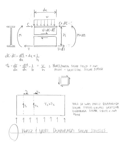
Your unit shear transfer into the chord is easy to calculate. It will match the unit shear in the deck perpendicular to the chord at that location and will, correspomdingly, be at a maximum near the supports. This is a consequence of the complementary nature of shear.

I don't often see floor decks with varying fastening but is common in longrr, untopped roof decks. Examples shown in Canam catalogs etc will reflect this.
 
KootK is correct, the longitudinal force in the chord, per lineal foot, at a given location is equal to the shear, per lineal foot, at that location. The longitudinal force in a chord is maximum at each end of the chord, decreasing in a linear fashion to zero at the center of the diaphragm.

DaveAtkins
 
I believe KootK and Dave have this right. The shear transfer into the chord is highest at the ends of the diaphragm. Think of it as a shear flow problem in a built-up beam (i.e. q=VQ/I). Shear on the cross section, V, is highest at the ends so that is where the shear flow, q, into the chords is the highest.

In practice, determine the shear transfer requirements for your fasteners at the end of the diaphragm and then either use that spacing along the entire chord length or reduce it near the center of the diaphragm if you want.

As KootK alludes to, it is common to see framing plan drawings for wood and metal deck roof diaphragms with zones of tighter fastener spacing near the ends and and wider fastener spacing near the center.
 
Dave, although I think we agree in principle, your wording is confusing me a bit. Isn't the actual longitudinal force in the chord highest at the center of the diaphragm, analogous to the bending stress in the extreme fiber of a simply supported beam? I guess when you say "per lineal foot", you aren't talking about the actual axial force in the chord, but the rate that axial force is increasing in the chord.
 
Thanks everyone for the responses and discussion.

The analogy of a built-up section makes perfect sense to me. The flanges of the built-up section take the tension/compression forces, while the weld between the web and flange is designed to transfer the shear flow into the flanges.

In the diaphragm case, the perimeter beams take the tension/compression forces (with the highest force at mid-span) and the puddle welds should be designed for shear flow (with the highest demand at each end).

I think my colleague was on the right track except had the force demands reversed. Thanks for the input everyone!

Peter
 
For shear studs in composite bridge girders, we do 2 checks - fatigue and ultimate strength.

The stress for the fatigue limit check is calculated using VQ/I for at least each tenth point along each span.

The ultimate strength check takes the ultimate compression capacity of the slab, or the ultimate tension capacity of the girder, whichever is smaller, and checks against the shear capacity of all the studs between the max moment location and the end of the span.

Edit: I should add that the "V" in the fatigue check is actually the range of shear values (Vmax - Vmin), which may not be significant in this case.
 
It sounds as though you've got this sorted structeng2. Still, I thought that you may find value in the attached sketch. I created it in a different millenium as a means to understanding these same concepts myself. I've never really had a mentor that excelled at diaphragm stuff so I'm mostly self-taught.

c01_orurkj.jpg
 
The resisting element at the ends isn't called a chord.....it's shear walls or struts. The transfer to them will be based on unit shear.

The chord is essentially the "flange" of the deep beam that is the diaphragm.
 
Status
Not open for further replies.

Part and Inventory Search

Sponsor