Eng-Tips is the largest engineering community on the Internet

Intelligent Work Forums for Engineering Professionals

  • Congratulations waross on being selected by the Eng-Tips community for having the most helpful posts in the forums last week. Way to Go!

Client requests V-shaped deck supports 1

Status
Not open for further replies.

StrucPatholgst

Structural
Jan 23, 2013
153
US
Have a client that proposed an idea for his deck. His house cantilevers two feet at the second floor, and he wants a long narrow 8' wide second-floor deck along the rear of the home. Originally he wanted zero deck columns, but with the width he's asking for, that will not be economically feasible for him. He now wants a minimum number of columns, and suggested either v-shaped or t-shaped supports every 12 feet. Since building code in his town won't allow a ledger at the rim joist of the house cantilever, the whole thing has to be self supporting.

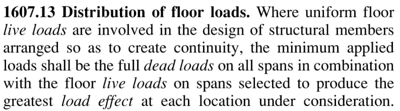
My question has to do with load cases. Normally your load cases address the joists, beams, etc. And if you just look at tributary area loads, the whole thing works great. But there will be unbalanced loads (folks standing along the railing, etc.) that will impart moment on the footing. Is there a standard anywhere regarding the degree of unbalanced loading to be accounted for on a deck or balcony? A bunch of 250 pound men standing shoulder to shoulder along the deck railing is roughly 60 psf. I would think 60 psf live load for the outer half of the tributary area would be enough to address the moment with the proposed support scheme. Any thoughts?

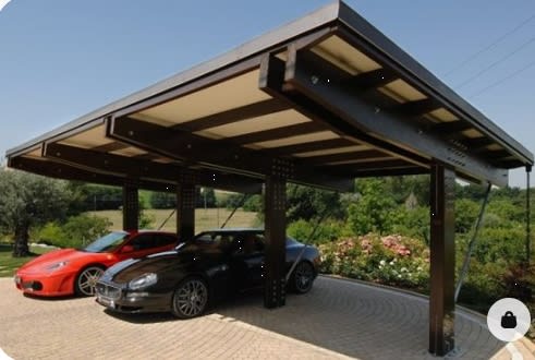
Here's what he's suggesting:

supports_uazqhf.jpg
 
Replies continue below

Recommended for you

Hey thanks for the reply. Skip loading is for roof live load reductions, though, no? At least that's what I use it for.
 
It is for roof and snow live loads yes, but it gives you a starting point because I can't recall any code prescriptions for floor pattern loading. Usually with floors I'll run a few calcs to find the worst case scenarios (all the people at one end, people on either end, people just in the middle, etc.).
 
Partial live loading is required by most codes. See the screenshots below from IBC and ASCE 7.

IBC_jxv6hl.jpg


ASCE_r9zhwe.jpg


Also, if the deck cannot be attached to the house, how will lateral loads be resisted? Cantilever columns?
 
R507.6.2 covers lateral restraint. Simpson sells hardware for this. The town doesn't allow vertical deck loads on a cantilevered floor joist, but lateral restraints are required.
 
what happens when you have uplift on the long overhanging side (and compression in the diagonal link) ?

"Hoffen wir mal, dass alles gut geht !"
General Paulus, Nov 1942, outside Stalingrad after the launch of Operation Uranus.
 
StrucPatholgst said:
R507.6.2 covers lateral restraint. Simpson sells hardware for this. The town doesn't allow vertical deck loads on a cantilevered floor joist, but lateral restraints are required.

R507.4.2 is for lateral restraint of the deck joists to prevent rollover, not the main lateral force resisting system. What prevents the independent deck structure from tipping over if it is not allowed to be connected to a ledger connected to the house?
 
Those Simpson DTT1Z tension ties might be able to handle the lateral loads in the direction perpendicular to the rim board. But you have two other problems you still need to solve. You also need to resist lateral loads in the direction parallel to the rim board. Also, I think you will probably end up violating the town's prohibition against adding gravity load to the cantilevered house joists unless you can come up with some vertically slotted connection details for both the out-of-plane and in-plane connectors that will not transfer vertical loads.
 
olddawgnewtricks said:
1. You also need to resist lateral loads in the direction parallel to the rim board.
2. Also, I think you will probably end up violating the town's prohibition against adding gravity load to the cantilevered house joists unless you can come up with some vertically slotted connection details for both the out-of-plane and in-plane connectors that will not transfer vertical loads.

Good points, thanks.
#1 can be addressed with shear restraint in final version of the deck supports
#2 can be fabricated. Vertical movement at this end of the cross beam in the V-support configuration, with 100 psf live load on the outer half of the deck surface, calculates out to 1/16" using exterior grade glulams, with 1100 lb lateral restraining (pulling) force, which would require a DTT1Z restraint every 4 joists.

Have not looked into a T-support yet.

 
This whole thing feels too sketchy for me for a deck. It's one thing to do it for a roof like in the OP, but decks and balconies aren't something I ever mess around with.

Just out of curiosity, why does the town not allow connection from a deck? I've never heard of that.
 
jersey - a ledger fastened to a rim joist that is sitting on a sill plate or a top plate of the wall below has a direct load path through bearing. If there's an overhang, then the load path is eccentric through a 3-nail connection of the rim joist into the end grain of the joists. Lots of failures have been caused by this.

StrucPatholgst - have you considered abandoning the prescriptive requirements and restrictions and engineering the complete load path? If you open up the soffit under the overhang, you can likely reinforce the joist to rim connection with Simpson angles - a GA or A34 installed with SD screws. I'd also resolve eccentricity with a SDWC truss screw in each joist through the rim about 3/4" down (check edge distance requirements). Then add the lateral restraints (which are the primary LFRS for a deck - it ties the the tension chord of a cantilevered diaphragm into the main diaphragm, albeit through the "lots-of-wood-things-nailed-together" load path approach). Not the little ones posted above, but the 3500lb option that goes into the floor system. It may require removal of floor finishes to improve fastening of the subfloor to the joists you tie to. Then you can put a single beam line out there, maybe with some decorative bracing to make it look neat.

If you go this route, make sure there are lots of pictures taken during construction that can be kept with record drawings. As I'm sure you know, once those connections are concealed this won't pass the 'smell test' for anyone inspecting the property later and the owner will need to be able to prove that it was done correctly without ripping it open for every prospective buyer/insurance agent.
 
I found a place in Vermont that actually designs, fabricates, and ships the arrangement I'm looking for, all in a kit.
 
Ah, didn't realize it said just for cantilever conditions. I thought it was just in general. Carry on.
 
Status
Not open for further replies.

Part and Inventory Search

Sponsor

Back
Top