Continue to Site

Eng-Tips is the largest engineering community on the Internet

Intelligent Work Forums for Engineering Professionals

  • Congratulations LittleInch on being selected by the Eng-Tips community for having the most helpful posts in the forums last week. Way to Go!

Clip Angle Weld AISC 10-3 4

Status
Not open for further replies.

Veer007

Civil/Environmental
Sep 7, 2016
379
Hey guys,

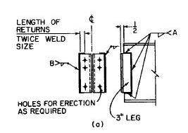
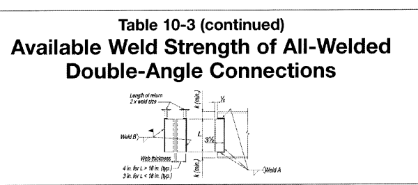
Just to be clear, why outstanding leg is welded only single side with 2t (t=weld size) return@top while web framing angle is welded 3 sides?

Can't weld outstanding leg also 3 sides?

Also, the 2t return helps prevent reverse loading?

Capture_xbv2k0.png


Thanks in advance!!
 
Replies continue below

Recommended for you

The lack of long returns allows the connection rotate at ultimate load. If you run the weld all the way to the heel of the angle, the weld would have to fracture for the the connection to rotate.
 
Rotational ductility, i.e. simple span beam end rotation, is allowed by flexure of the outstanding angle legs. The 2t return prevents the fillet weld from rotating and experiencing tension at the weld root.
 
Ah yes, this issue. There was a long discussion about this type of connection on Eng-Tips some time ago. It's a crazy long / meandering thread, so I won't post it (plus I'd have trouble finding it).

However, I will try to provide a basic summary (as I remember it):

1) AISC 15th edition manual page 10-7: "Line welds are placed along the toes of the angles with a return at the top"
2) On that same page: "Note that welding across the entire top of the angles must be avoided as it inhibits the flexibility and, therefore, the necessary end rotation of the connection". That's what phamENG and sbisteel were getting at.
3) But, why have a return at all? I believe that they don't want the fillet root to be placed in axial tensions which could result in fracture at the weld. A small return greatly improves the behavior and lessens the chance of fracture.
 
The simple fact is the horizontal welds on the outstanding legs are not required for strength. See the liked thread for the need of the "returns". Link
 
Hey, guys for simple shear it would be fine, but the beam has an axial force about ±20kips, so we are discussing to provide weld at the entire heel of an angle for both top and bottom, doesn't it fine?

otherwise, I'll provide top and bottom flange plates.

Thanks in advance!!
 
doesn't it fine?

I don't see why not. You should have included this load in your original question to get correct answers.
 
No, I don't think it is fine. And unless it was designed as a moment connection (which is unlikely based on the fact that you want to use a standard shear connection), I wouldn't use flange plates, either.

Not sure of the vertical load or beam/column sizes, but can you get a single plate shear connection to work? Weld it to the column, bolt it to the beam and you'll be fine as long as the loads work out. Depending on the nature of the axial load, you may need to use slip critical bolts, but that would probably be a question for the EOR.
 
Double angles are not appropriate connections for transferring axial load - agree with phamENG about the single shear plate. You can only weld the heel of one of the angles, so only half of your connection will transfer the axial load...and with that one angle welded on the heel and the other not, I would assume the angle with the additional weld would end up taking the bulk of the shear as well (the angle with the unwelded heel needs to deform slightly to transfer the shear to the weld on the outstanding leg whereas the other angle does not). At that point you should just use a single shear tab or single angle.

 
Single plate connection may not work out for your loads. The detail provided is quite common simple framing connection prior to the single plate connection gaining popularity. Add bolts to work together, if necessary.

image_m9lk3u.png
 
r13 said:
Add bolts to work together, if necessary.
absolutely don't do this, welds and bolts cannot be used together. The nature of there being some small slip required at the bolt hole prior to engaging the bolt and the small deformation/load response from the weld means you need to rupture the weld before properly engaging the bolts.

My Personal Open Source Structural Applications:

Open Source Structural GitHub Group:
 
r13, the bolts shown in your detail are labelled as erection bolts. As Celt83 noted, don't mix bolts and welds for in service design loads. What you're showing is essentially an end plate, so make it a bolted end plate and forget about the double angles.

 
My thoughts on axial load:

1) This type of connection is not generally used for axial load. See the long / meandering thread from 2014. So, be very careful if you've got significant axial load in the connection. The thread is partly related to my attempts to come up with a rational way to come up with an axial capacity for this type of connection for the program that the company I used to work for was developing.

2) Putting a weld across the entire top of the connection probably violates the rotational ductility provision. Meaning that the connection is too rigid to be considered a pinnned connection. Though it's probably not rigid enough to be a fixed condition. Pretty tricky.

3) Generally speaking it, is NOT good to assume that bolts and welds will share load. The reason being that the welds tend to be more rigid and take the load. Then they fracture before the bolt see any load. See AISC 15th edition Section J1.8 "Bolts shall not be considered as sharing the load in combination with welds, except in the design of shear connections on a common faying surface where train compatibility between the bolts and welds is considered". It goes on to say that the welds must be designed for at least 50% or 70% of the connection depending on the tightening method for the bolts.

If you are to do something like this, I would suggest that the shear strength should be based on the welds only. Then the axial strength be taken based on the bolts only.
 
The bolt and the weld should not be considered "sharing the load" for "bearing type connection" (weld takes 100% shear force). It was permitted for "slip critical" type connections (at least up to the 9th Ed).
 
Yeah, I think so, welded bolted combination should be considered as slip critical condition.

Thanks in advance!!
 
Veer007,

Glad that you got the message. Double check the current code though.
 
What I have done when there is an axial load and a shear load at a pinned connection is either use a single shear plate, as mentioned above, or a double angle connection with the legs welded to the supported beam and the outstanding legs bolted to the supporting member. You have to check prying with this connection, however.

DaveAtkins
 
I have to agree with Dave that his configuration would be preferable. And, probably easier to erect too.
 
My vote goes to DA's suggestion too.
 
Status
Not open for further replies.

Part and Inventory Search

Sponsor