Continue to Site

Eng-Tips is the largest engineering community on the Internet

Intelligent Work Forums for Engineering Professionals

  • Congratulations KootK on being selected by the Eng-Tips community for having the most helpful posts in the forums last week. Way to Go!

Cold Form Track Weak Axis Bending

Status
Not open for further replies.

sticksandtriangles

Structural
Apr 7, 2015
472
Hello,

I am designing a building where we are utilizing the Ecospan composite floor system as our main floor framing system.
This system will be bear on metal studs that are assumed to be spaced at 16"oc. As I understand the system, if studs and joists are not aligned in direct bearing, the top track must be designed for the pre-composite load of the floor system delivered to the track, before the load distribution member develops the ability to distribute load.

This is where I get a little lost in the cold form design process. Using the AISI 2012 specification I first check section C3.1.1 for flexural strength of the track. Seems pretty easy following procedure 1 - based on the initiation of yielding, basic M.n=(Section Modulus * Fy) stuff.

Then, am I also required to check individual elements of the track per section B2 of the specification? Specifically, the top of the track will be in compression which I am picturing as an element in uniform compression stiffened on both edges. The equations in in this section look pretty convoluted and I did not know if purely checking section C3 was sufficient to say that the track can resist the moment. Because the initial yielding is in tension, I need to calculate the effective section of the track, which upon looking up examples of calculating effective sections, looks very complicated too me.
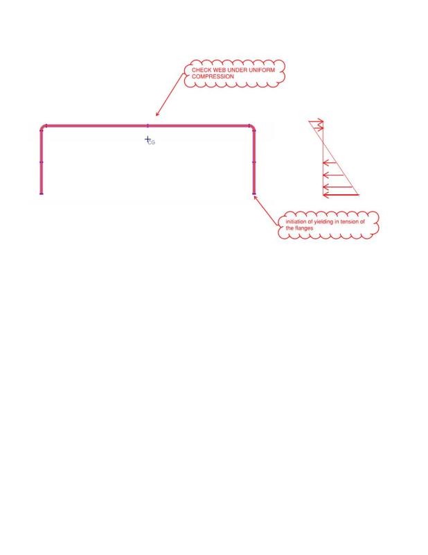
eNG_TIPS_xtxa3a.jpg


Also, if this section B2 does apply, is there any software that can aide in these calculations? I have a good amount of software available to me, but none of the more general packages seem to have any good CFS design checks (SAP RAM Risa).

Thanks in advance for the help.
S&T
 
Replies continue below

Recommended for you

for my money, I would not check the web as a panel in compression.

I think you need to determine how much of the web is effective; I'd start with 30t, there's an iterative procedure to check this ...
assume an effective width,
calculate the stress in the web,
calculate the critical compression stress for the web,
adjust initial assumption as required.

another day in paradise, or is paradise one day closer ?
 
S&T...

I would never bear OWSJ (Open Web Steel Joists) directly on a weak axis CFS (Cold-Formed Steel) track.

I design OWSJ roof and floor systems as well as CFS horizontal and vertical systems. Having never heard of the "ecospan" system, i watched the video to the link you provided. Apparently the "ecospan" system is nothing "new" in construction standards as it is basically and primarily OWSJ... What apparenlty IS new, is the "E" series OWSJ as opposed to the currently common "K", "LH" and "DLH" series.

At +/- 2:24 on the video, you'll notice that the OWSJ bear on (perhaps) a continuous HSS square or rectangular tube, which, THEN bears on top of the CF steel studs. Throughout the majority of the video you'll notice that the steel joists bear directly on top of wide flange steel beams or open-web girders.

At +/- 5:50 on the video, although it is stated that the OWSJ "ecosystem" is "COMPATIBLE WITH ANY LOAD BEARING WALL FRAMING SYSTEM", and then at +/- 5:54, the video DOES show the system on "LIGHT GAGE CFS" studs, notice this portion of the video is animated and NOT reasonable. Do NOT... I repeat... DO NOT bear your steel joists directly on top of a track without either a significant acceptable stud below it or the continuous HSS or other acceptable "runner" above the track.

A (typical) CFS track CANNOT support such a load.

A typical CFS track cannot even (reasonably) support a CFS joist over a short-span dustcover.

You'll need to reconsider what the steel joists are bearing on. Likely a wide-flange or the HHS similar to 2:24 of the video.
 
S&T... I edited my post... please re-read above...
 
rb1957, I am new to CFS design and was wondering why I even need to calculate how much effectiveness there is in the web? Is it assumed that the stiffest part of the web (i.e. where the flanges stiffen the element) will only take the compressive load?

Do you often find these element checks to control the design of members? Or does the member check typically govern the design of cold form members?

Thanks for your post BSVBD. I have design example calculations from a CFS designer that "proves" that a beefy track (600T350-68) can take the point load from a joist. They simply follow the flexural component checks found in C3.1.1 and calculate a minimum section modulus required. They do not perform any element checks as I described above. I want to make sure they have checked everything as well, as like you said, sitting a joist on little track does not intuitively feel OK.

Thanks
 
the "web" is the flat bit between the flanges, as you've labelled. It may not be fully effective, depending on geometry. I picked up on your use of "effective section" and figured this is what you meant. If the compression from bending is less than the buckling allowable then you're GTG.

If it were my beam, and it's principally loaded in bending, I'd form lips at the ends of the flanges.

Looking at the video they seemed to be laying a concrete floor on a continuous corrugated panel. How does your open section fit into this ?

another day in paradise, or is paradise one day closer ?
 
Position a stud directly under each joist--then you need not worry about any of this.

DaveAtkins
 
You are preaching to the choir Dave.

The ease of construction they say... is it really that hard to align studs and joists?
 
DaveAtkins said:
Position a stud directly under each joist--then you need not worry about any of this.
Agreed or use (2) back to back to eliminate the need for questionable bridging.
Ain't no way a 14ga track will do this unless the load is light.
I would be using the tube steel distribution member so you do not have to worry about them getting the studs in the right place. It makes everything work better including giving you something nice to attach shearwall straps to.
 
SNT said:
Specifically, the top of the track will be in compression which I am picturing as an element in uniform compression stiffened on both edges.

In terms of evaluating local buckling, I think that the critical scenario will be over top of studs when the track flanges are in compression. Folks debate this and some just treat the track as simple spanning, assuming that the flanges will just buckle out of the way. I question how much shear capacity you have once the flanges buckle. It's also possible that positive moment in an end span condition may govern.

SNT said:
I am designing a building where we are utilizing the Ecospan composite floor system as our main floor framing system.

They came out to my office for a lunch and learn last year. A representative of Lochsa Engineering (Idaho) came along as Lochsa seems to be their partner engineer for a lot of the ecospan projects. They really seemed to know their stuff and they're banging out very economical, low-mid rise buildings in Idaho and Nevada like nobody's business. The Lochsa guy was great and made himself available to answer my questions after the fact. Ecospan might be able to put you in touch with Lochsa for tech support if you like.

SNT said:
the top track must be designed for the pre-composite load of the floor system delivered to the track, before the load distribution member develops the ability to distribute load.

This was my one point of contention with this system. As I see it, any load delivered to the joist, at the level of the joist, must be resisted by the track regardless of whether the distribution member is there doing it's thing or not. That would include:

1) Self weight and super imposed dead load of the floor system at the same level as the track.
2) Live loads imposed on the floor system at the same level as the track.

I like to debate structural engineering theory -- a lot. If I challenge you on something, know that I'm doing so because I respect your opinion enough to either change it or adopt it.
 
Thanks for your thoughts Koot.
KootK said:
This was my one point of contention with this system. As I see it, any load delivered to the joist, at the level of the joist, must be resisted by the track regardless of whether the distribution member is there doing it's thing or not. That would include:
I agree with you that the load transfer mechanism they describe in their pamphlet is somewhat questionable for transferring the post-composite load to the load distribution member. It looks like they rely on the self drilling composite screws to engage some sort of concrete breakout cone with justification through strut and tie methods. Not sure how much I buy this.

This whole project seems a little odd to me as the floor systems is by Ecospan and the wall framing is delegated cold form design. Me as the EOR is left in an odd spot questioning how much do I need to provide to these two seperate entities to ensure they are designing for the correct loads etc. I am finding my self designing a lot of the cold form members to verify that the CFS designer is not left in a pickle. How do you guys handle jobs like these? When I design a steel beam I know exactly what is going on and just delegate the connection design as I know shear tabs will work for a majority of the cases. Maybe I need to trust that this has been done before and the Ecospan guys and CFS designer can get the job done for a majority of the typical situations.

Also, not sure if you guys have seen their design pamphlet on the concrete distribution member, but the design of that is a dousy. Load Distribution Member Strut and tie method all over the place. Of course Ecospan says they do not design this member either. I am dusting off the strut and tie books and ruining project profitability trying to justify this thing works. It seems so small too, an 8"x6" element should not warrant this much attention!!!
 
sticksandtriangles said:
I am finding my self designing a lot of the cold form members to verify that the CFS designer is not left in a pickle. How do you guys handle jobs like these?

Yes, IMHO, you need to be familiar enough with the limitations of the delegated design systems so the CFS designer and his installer (who bid the job prior to getting it engineered) are not left in a pickle. It has happened to me countless times. I would show an HSS distribution member. At least that way, they are covered in their bid and can lighten things up, if possible, to save some money. It will make the job go much smoother.
 
SNT said:
Thanks for your thoughts Koot.

Happy to help. Or at least attempt to.

SNT said:
It looks like they rely on the self drilling composite screws to engage some sort of concrete breakout cone with justification through strut and tie methods. Not sure how much I buy this.

My understanding is different and goes like this:

1) The screws are used to make the slab composite with the joists. It's testing based so I've no issues with it.

2) The composite behavior of the joists, or the lack there of, has no effect whatsoever on the OWSJ reaction on the track/distribution members.

3) The distribution member is unaffected by the screws. It's straight up strut and tie with the tie being on the top of the distribution member. That's what threw mew off initially. I was thinking of the distribution member as a conventional beam and wondering how it could possibly work with no continuous bottom steel. But the STM checks out, at least at interior locations which is most of them.

SNT said:
It seems so small too, an 8"x6" element should not warrant this much attention!!!

I wouldn't give it any. With 16" o/c studs, your shallowest strut angle is 45 degrees-ish. Given the minor loads capable of being delivered to this system by the CFM, I'd deem it okay by inspection. Certainly, I've seen examples of this system being used in buildings up to eight stories with no issues cropping up due to failure of the distribution member to perform. As I mentioned though, I only consider the distribution member to be effective for loads being delivered to the top of that distribution member. That still leaves the track very much on the hook for some load, even in the finished condition.

SNT said:
I am finding my self designing a lot of the cold form members to verify that the CFS designer is not left in a pickle. How do you guys handle jobs like these?

Unless you have considerable expertise in the design of the delegated components, there's some risk that is difficult to avoid without burning your fee out of existence. I feel the same way about precast parking facilities. My role sometimes feels like little more than "Yeah, I'm thinking beams, columns, and double tees. We good?". I think that communication is your best friend here. Talk to the ecospan guys, their engineers, and any CFM guys that will have you to gauge the reasonableness of what you're proposing. This stuff has all been done before so the various parties should have a good sense for what works. You're already well on your way here with XR250, one the best CFM guys around. A reluctant expert is still an expert, perhaps the best expert.

I like to debate structural engineering theory -- a lot. If I challenge you on something, know that I'm doing so because I respect your opinion enough to either change it or adopt it.
 
KootK said:
You're already well on your way here with XR250, one the best CFM guys around

Thanks for the kind words. not sure if it is true or not, however. After my last light gage job almost killed me, I may not be doing anymore of them. The entire process of how EOR's and contractor's handle CFS just ain't right. The advent of BIM makes horrible details. The installers miss about 50% of the details on the plans and you are stuck sticking your neck out in order to fix it. I could go on..
I got plenty of work where I am the EOR - much nicer!
 
Status
Not open for further replies.

Part and Inventory Search

Sponsor