trackman417
Civil/Environmental
Came across something I did not find in any of the forum posts. Thought this would be interesting to discuss
Note: Collar ties referenced here-in are for ties that are in the upper third of the roof system.
All of my analyses are performed by skyciv.
For replication, my nodes are(x,y,z)(in feet):
Main Members/rafters(2X12's):
-(0,0,0)
-(12,9.33333,0)
-(24,0,0)
Collar Ties:
-(9,7,0)
-(15,7,0)
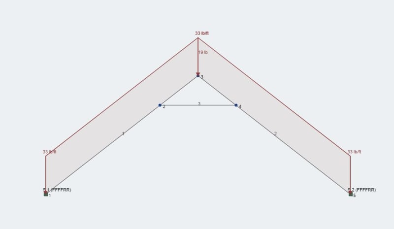
This is a setup for a house with a 8:12 gable roof that is 24' wide and 9'-4" tall. Collar ties 3 feet below the top of ridge.
Setup One:
Setup One Results:
Setup Two:
Setup Two Results:
Every post I have read about collar ties and their inability to soak up thrust from this setup seem to stem from models having both rafters fully pinned rafters at the top plates. This does not seem like a very realistic model as the walls themselves CAN and WILL deflect in the x-direction.
Setup 1 seems to be a very realistic case where the walls can and will move to allow the collar ties to soak up the thrust generated from loading. Although, I do not think IBC takes into account these loads and a the collar tie connection to rafter must be designed.
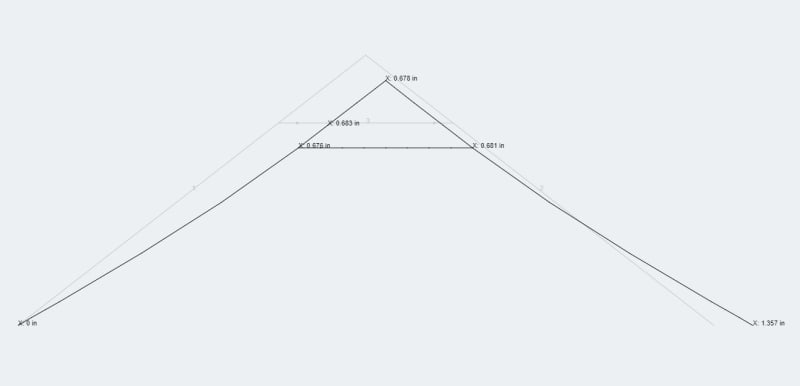
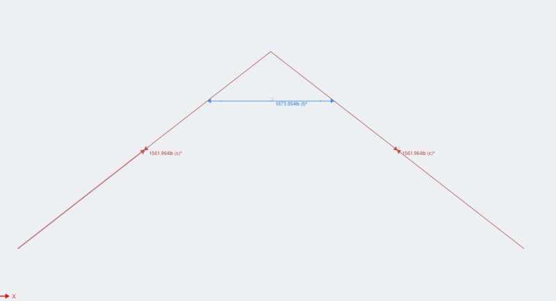
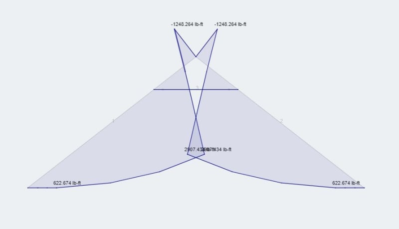
Pictures are:
Thoughts?
Note: Collar ties referenced here-in are for ties that are in the upper third of the roof system.
All of my analyses are performed by skyciv.
For replication, my nodes are(x,y,z)(in feet):
Main Members/rafters(2X12's):
-(0,0,0)
-(12,9.33333,0)
-(24,0,0)
Collar Ties:
-(9,7,0)
-(15,7,0)
This is a setup for a house with a 8:12 gable roof that is 24' wide and 9'-4" tall. Collar ties 3 feet below the top of ridge.
Setup One:
The rafters sit on the top plates of a structural load bearing wall that is about 4 feet above a toe plate.
I used one pin(rotation free, x & y fixed) at coordinate (0,0,0).
The other end received a quasi pin(rotation free, y fixed, x free).
This will allow the whole system to try and relax as the roof gets more load thrown at it.
I used one pin(rotation free, x & y fixed) at coordinate (0,0,0).
The other end received a quasi pin(rotation free, y fixed, x free).
This will allow the whole system to try and relax as the roof gets more load thrown at it.
Setup One Results:
Collar ties take all tension(approaching 1900lb) as the wall is allowed to deflect
X-direction deflection is 1.357 inches
Assuming both walls deflect the same amount, we have .67inches on each side of the wall
X-direction deflection is 1.357 inches
Assuming both walls deflect the same amount, we have .67inches on each side of the wall
Setup Two:
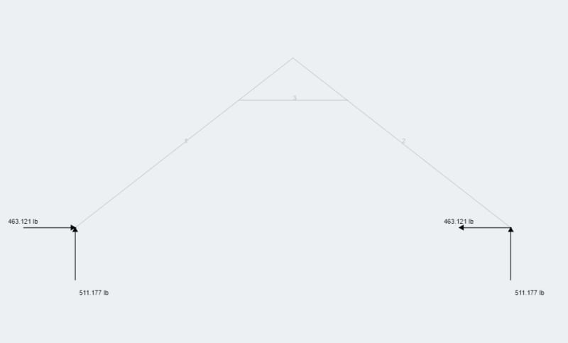
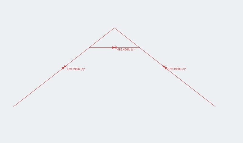
Same as setup one, with the exception we have two "typical" pins holding both sets of rafters into place.
Setup Two Results:
Collar ties take only compression (550lb) and the walls soak up the resulting thrust from the setup(460lb)
Every post I have read about collar ties and their inability to soak up thrust from this setup seem to stem from models having both rafters fully pinned rafters at the top plates. This does not seem like a very realistic model as the walls themselves CAN and WILL deflect in the x-direction.
Setup 1 seems to be a very realistic case where the walls can and will move to allow the collar ties to soak up the thrust generated from loading. Although, I do not think IBC takes into account these loads and a the collar tie connection to rafter must be designed.
Pictures are:
Loading
-Setup 1 deflection, axial loading, moment
-Setup 2 deflection, axial loading
-Setup 1 deflection, axial loading, moment
-Setup 2 deflection, axial loading
Thoughts?


