Continue to Site

Eng-Tips is the largest engineering community on the Internet

Intelligent Work Forums for Engineering Professionals

  • Congratulations The Obturator on being selected by the Eng-Tips community for having the most helpful posts in the forums last week. Way to Go!

Collar ties at every row of underpurlins?

Status
Not open for further replies.

Tomfh

Structural
Feb 27, 2005
3,439
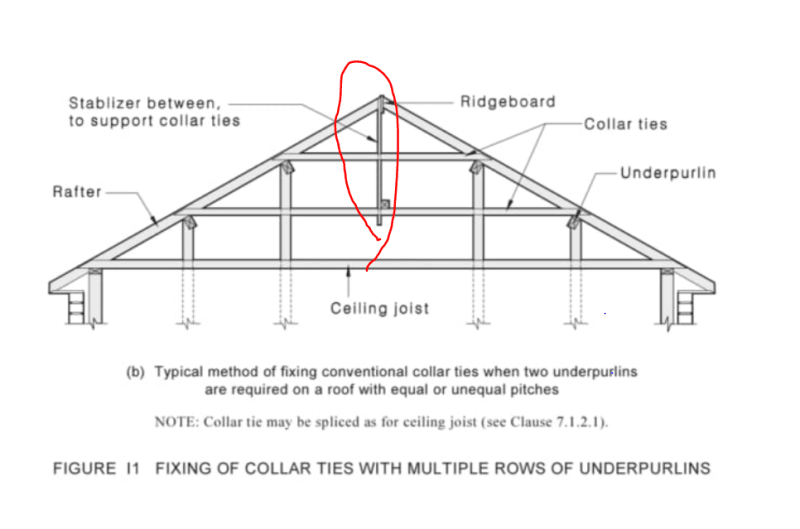
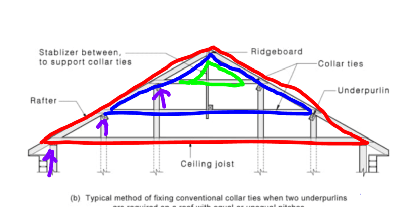
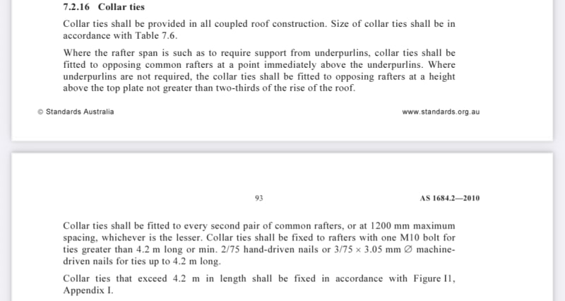
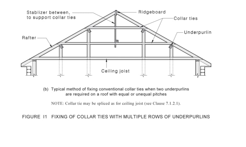
AS1684.2-2010 (Timber Framing Code) says that collar ties are to be provided at each row of underpurlins:
83166E86-4A3A-46FB-ABCA-76CF124379DB_mlbpdw.jpg

6E4A8685-185D-4C2D-ACCB-71CA679099BE_mjbbbl.jpg


This rule is often ignored in Australia at underpurlins. There will be collar ties at the top, but there will often be underpurlins which do not have a corresponding collar tie. Eg the red arrow below:

4AEE5275-7810-46EB-B8D0-425ACF3373F9_wosrv1.jpg


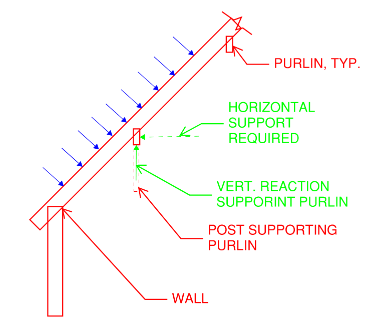
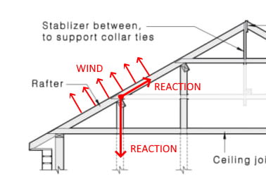
What is the structural logic driving the blanket rule for collar ties at every underpurlin? How do people get around the rule eg attic conversions?

Does this rule apply in your country too?
 
Replies continue below

Recommended for you

In the states, this describes a rafter tie, though we have no such rule for purlins that I'm aware of.

We have collar ties, but they are in the upper third rather than the lower a described in your code.

So in your context, it makes some sense. Look at a free body diagram of the roof. You'll have a reaction at that point that isn't always vertical. So that collar tie provides a horizontal reaction that helps resolve the non-orthaganol loading. (Particularly important for wind, which is often asked to act perpendicular to the surface.)
 
phamEnd said:
Look at a free body diagram of the roof. You'll have a reaction at that point that isn't always vertical. So that collar tie provides a horizontal reaction that helps resolve the non-orthaganol loading. (Particularly important for wind, which is often asked to act perpendicular to the surface.)

Why can't the orthogonal component be resolved along the rafter?
 
Tomfh - in the case of wind load applied normal to the surface of the roof, it can't be resolved along the rafter because it's at 90 degrees to the rafter. See the sketch below. The purlin supporting the rafters has to either span between two supports capable of resisting vertical and horizontal load (such as large timber trusses), or it has to be supported by discreet members. I get the impression that the code section you cite is referring to light frame construction where heavy timber trusses would not be used. So something has to resist that load - enter the "collar" tie (as your code calls them - again, rafter tie in the states to keep things clear). There is probably an argument to be made for diaphragm action, but it's my understanding that in your part of the world it's common to use flat strapping with large gaps and roofing overtop of that - correct? If so, I wouldn't expect as much diaphragm action as a fully fastened field of plywood.

Screenshot_2022-09-12_065726_rxnoit.png


Here's a shot from my residential code. It has a similar requirement, but it allows us to take it down to the ceiling as long as the ceiling is either a diaphragm or is otherwise sufficiently braced.

Screenshot_2022-09-12_070511_zffp0p.png
 
tomfh said:
Does this rule apply in your country too?

Not to my knowledge.

tomfh said:
What is the structural logic driving the blanket rule for collar ties at every underpurlin?

When I look at the setup, it seems to me that, by the book, it only works for loadings that are symmetrical-ish about the gable roof. As such, I hypothesize that the intent is:

1) Not to deal with wind except at the upper most collar. Wind is usually quite asymmetrical in nature.

2) To deal with gravity loads: dead and snow mostly.

3) To eliminate -- or reduce -- the need to deal with horizontal reactions at the underpurlin supports which can be onerous depending on the setup.

tomfh said:
How do people get around the rule eg attic conversions?

If one were to accept my logic above, the way to deal with it would be to engineer the system for those failure modes which might have been ameliorated by the presence of the collar ties. Whether or not this would be acceptable, to the AU AHJ, I couldn't say.


phamEng said:
Tomfh - in the case of wind load applied normal to the surface of the roof, it can't be resolved along the rafter because it's at 90 degrees to the rafter

From a structural mechanics point of view the horizontal component going into the tie could be resolved along the rafter. :

6E4A8685-185D-4C2D-ACCB-71CA679099BE_mjbbbl_aroxpj.jpg


There are many other cases in the code where this explicitly occurs, i.e. where a strut (or beam) is supporting a rafter at angles other than 90 degrees. E.g. here in a non coupled roof:

Capture2_wasdqr.jpg


Is it the rule in your code that struts must be at 90 degees to rafters?


Also, these collar ties are just ties. They're not required for gravity/downward loading. The code nominated collar ties will often have close to zero compression capacity, so it's a tension thing only, as far as I can tell. I still don't understand why each and every underpurlin needs one.
 
Kootk said:
1) Not to deal with wind except at the upper most collar. Wind is usually quite asymmetrical in natur

Agree it's largely due to wind. My understanding was the collar tie helps keeps the ridge connection closed shut.

Kootk said:
2) To deal with gravity loads: dead and snow mostly.

They're only ties though? Say I need a 10m long collar tie. The code says to use a 120x35 member. Not much gravity capacity there. The thrust is going down the strut and back into the rafter.

Kootk said:
3) To eliminate -- or reduce -- the need to deal with horizontal reactions at the underpurlin supports which can be onerous depending on the setup.

Yeah I was wondering that, but there are so many cases in the code that are at least as bad in terms of non orthogonal struts, which the code happily accepts, e.g. my image above.
 
Tomfh said:
They're only ties though?

Are they? I took the requirement below to mean that some compression capacity was intended. Or are you thinking that this is just the sag rod of the timber-sphere?

C01_djhpmz.png
 
Tomfh:
The two methods look like two ways to skin the same cat, as long as an intelligent engineer with some knowledge and experience can rationalize his/her particular detail, with well-established principles of mechanics. I think I would rather rip a slope on the top edge of the purlin to match the rafter slope, and have the purlin sit flat/horiz. on the end of the post below. Then apply some framing anchors to resolve the load components btwn. the purlin and the rafter. The spacing of this detail depends on the loads, the support conditions below, and the diaphragm strength in the plane of the roof. The code requirement cited in OP is their (code writers and AHJ’s) effort to take any thinking out of the process, partly in recognition of the fact that there are so many people doing little thinking while at the same time calling themselves engineers and practicing that profession. Remember, we have democratized the codes, so any damn fool can do this stuff as long as they can read and understand an ever more complex and verbose set of codes intended to cover all the possible details and structural conditions in the universe and beyond. They really complexify things when they try to cover all conditions, to accommodate everyone and anyone, without any real structural knowledge or thinking on the part of that detailer, builder, whoever, being needed to pretend to do this design and analysis. The codes have pretty much written the real Structural Engineering process out of the process, by trying to produce a cookbook approach which covers everything. Just follow their recipe and you don’t even have to care what the salt or leavening is intended to do. And, you are a baker or an engineer. Then comes Tomfh with a legitimate question that they still haven’t covered with their dumbed down code for all people.
 
Kootk said:
Are they? I took the requirement below to mean that some compression capacity was intended. Or are you thinking that this is just the sag rod of the timber-sphere?

I assumed the intent of these collar ties is tension only (hence "tie"), however I'm not 100% sure. The code prescribes 70x35 for collar ties up to 4.2mm and 90x35 for ties over 4.2m, which seems very slender for something intended to take compression.
 
I agree that most anything prescriptive can be engineered around by way of skilled engineering. At the same time, however, most of this stuff originates from the sound wisdom of our predecessors. So, like Tomfh, I'm reluctant to discard it unless I'm confident that I understand it. Babies & bathwater etc.

I think that I've got this now. New hypothesis:

1) I still feel that this is primarily for gravity loads.

2) I propose that the intent is to create "trusses within trusses" as shown below. This, to accomplish the following:

a) I imagine that one designs all of the rafter supports to carry, roughly, equal shares of the gravity load. Without the tension ties and the faux trusses that they create, I would guess that the stiffness of the red truss below would tend to dominate over the flexural stiffness of the underpulins.

b) Using the "under trusses" to shield the red truss from excess load also shields the rafter to ceiling tie connection from excess load.

C01_pnq45z.png
 
Status
Not open for further replies.

Part and Inventory Search

Sponsor