Continue to Site

Eng-Tips is the largest engineering community on the Internet

Intelligent Work Forums for Engineering Professionals

  • Congratulations SDETERS on being selected by the Eng-Tips community for having the most helpful posts in the forums last week. Way to Go!

Column 3D Interaction Surface vs Code Biaxial Formulae

Status
Not open for further replies.

Trenno

Structural
Feb 5, 2014
831
What are the major benefits to defining the 3D interaction/failure surface over using codified bi-axial bending column clauses?

I assume with the exponents in the unity equation they result in generally conservative capacities? Whereas you may be able to squeeze more capacity from full 3D interaction surfaces?

 
Replies continue below

Recommended for you

Yes and yes basically. Quite a bit more capacity usually depending on the form of the biaxial equation.
 
Interesting. Thanks Agent.

Here's one I've not yet come across a definitive answer - how would one define the utilisation ratio for a design point (N, Mx, My) within a failure surface?

Take a horizontal cut at a constant Axial Load (N) and then draw a line through the (Mx, My) coordinate to hit the failure curve. Then it's simply the ratio of how close the design point is to the curve?

 
I kinda wish we stuck with the interaction equation rather than the 3D surface. In most cases, I don't feel that the improvement justifies the complexity. But, you know... computers.

Trenno said:
Here's one I've not yet come across a definitive answer - how would one define the utilisation ratio for a design point (N, Mx, My) within a failure surface?

1) For a given load case, draw the straight from the origin, through that load, extended out to the failure surface.

2) Utilization = [lengh along line from origin to load ]/ [length along line from origin to surface].
 
From 0,0,0 point extend a line through your N, Mx, My point and carry on to the surface.

If axial loads are proportional to the moment (which they often can be) this gives you a feel for how much you can scale all three components to hit the failure surface.

Often though you'll just see at this N, the moment ratio is x.xx, working in the Mx, My plane.

I'm not aware of any standard convention for it. But expressing it in a similar way to the code biaxial check might be a good starting point (whatever form that takes in your code). Usually this is a ratio of moments being less than 1.0?
 
Trenno said:
Take a horizontal cut at a constant Axial Load (N) and then draw a line through the (Mx, My) coordinate to hit the failure curve. Then it's simply the ratio of how close the design point is to the curve?
yep, could do a vertical cut at the angle = tan -1(Mx/My) and get the interaction surface for a constant Mx, My relationship.

Open Source Structural Applications:
 
What is your codes interaction equation by the way? I didn't know that was still a thing.
 
KootK said:
But, you know... computers.

With a little C# coding, you can get a nice surface with 0.5 degree increments with a click of a button!

 
One area where you need to use the true interaction surface is if you're working out overstrength capacities for use in capacity design. Using an approximation will potentially underestimate the demand on capacity deign protected elements.
 
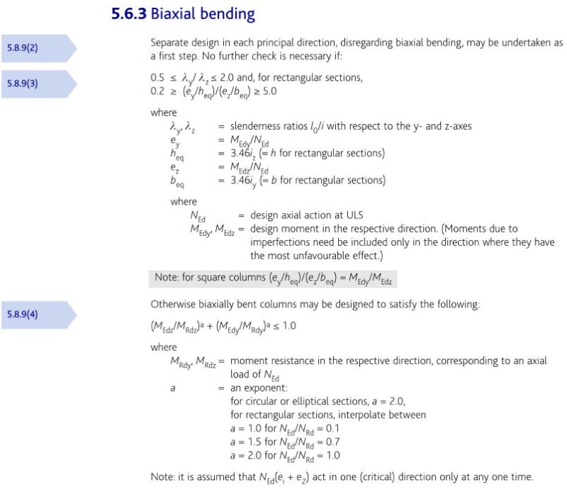
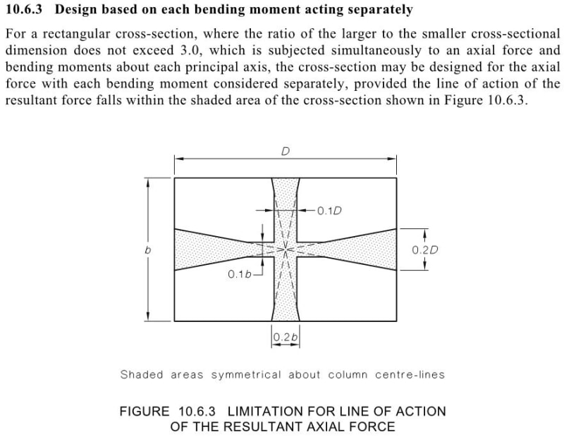
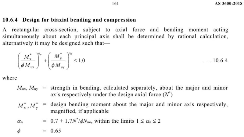
KootK, below are the extracts from two codes that I'm most familiar with: EC2 and AS3600.

b1_da0ygn.jpg


b2_pfjdij.jpg


b3_avc5bp.jpg
 
Celt83 said:
yep, could do a vertical cut at the angle = tan -1(Mx/My) and get the interaction surface for a constant Mx, My relationship.

This means you'll have to take planes/cuts through each design point (ie each load combination), could be a bit computationally expensive.

Might have to cull the insignificant design points beforehand, but then what would that process be... some points could be above the balance points, some could be below...


PS. agree, it should "little"... I was just being facetious about KootK's old school methods Stockholm syndrome. Someone smarter than me can do the final coding!

 
Trenno, as a comparison point, in the New Zealand code there is no similar relationship. The expectation is you analyse a section from first principles if you have bending and axial loads acting on a section. The capacity is there, so make the most of it rather than accept the simplification.

You've got me thinking if there's ever going to be a scenario where the simplification might be unconservative, weird section shapes and reinforcement layouts can sometimes result in some fairly deformed looking Mx/My slices.
 
Be careful with the 10.6.4 equation based on Mx and My. It came from steel design rules where the stress/strain material properties are very different to concrete. We have done comparisons and found it can be un-conservative by up to 40%. That is why the phi factor was re-defined in 2018 as .65 in the combination formula, where previously it was the phi at Mx and My used and they could have been .8 (now .85 in the 2018 code).

We first noticed the problem several years ago when comparing a square column in RAPT at 45 degrees compared to Mx and My at 0 and 90. Even though RAPT does not do biaxial, for a square symmetric column at 45 degrees its results are a correct bi-axial solution. For heavily reinforced columns, there was very little increase in capacity at 45 degrees due to the shape of the compression zone (triangular with 0 width at the extreme compression face) and the resulting much deeper neutral axis.

Inherent inaccuracies in the rectangular stress block for non-square section shapes at the 45 degree rotation compared to the square compression faces at 0 and 90 degrees do not help.

The approximate method in 10.6.3 combining Mx and My shows a very large increase in capacity.
 
Rapt - that's interesting. So would you suggest trying to define the 3D interaction surface? But then it sounds like there are slight limitations with also regarding the stress block?

 
If you want any degree of accuracy, you at least need to do a true biaxial analysis and use a proper stress strain curve. But it would depend on how the interaction surface was generated. It would have to determine the angle of the resultant in each case. I know RAPT does not do this. I do not know what other programs do. There was a theorum for generating there years ago, I think it was Greene's Theorum. But my impression of it was that it still used Mx and My to generate Mxy at any rotation, so I doubt it would account for the changing phi factors.

We find the rectangular stress blocks to be very inaccurate from decompression to balanced. At pure axial and pure bending they are normally ok for rectangular sections. As soon as the section is not rectangular (never ever is for biaxial) then they become even less accurate.

And using phi capacity factors are very inaccurate for Mx, My methods as they vary so much depending on neutral axis depth.

In general Material factors like Eurocodes are much better for column interaction diagrams as they automatically account for variations in concrete and steel contributions and ductility.
 
Thanks for that Trenno. The last time I saw column design as an interaction equation, it was in a book by fling published in the 70's and was a much simpler thing. I imagine that the accuracy issues were a bit less of a concern back when a "column" was something to the tune of 16" x 18" rather than today's more exotic 6" x 48" stuff.
 
Lucky these days I work with EC2 instead of AS3600.

I'm curious to explore this further.

I found a little explanation of the method you describe Rapt,

Link

 
Status
Not open for further replies.

Part and Inventory Search

Sponsor