Continue to Site

Eng-Tips is the largest engineering community on the Internet

Intelligent Work Forums for Engineering Professionals

  • Congratulations Danlap on being selected by the Eng-Tips community for having the most helpful posts in the forums last week. Way to Go!

Column Buckling

Windnut

Mechanical
Apr 24, 2005
5
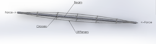
I have attached a drawing of a beam with crosses and stiffeners. Does anyone know if there is a name for this type of truss? Does anyone know formulas for calculating the maximum critical buckling load when the beam is put into compression? How about formulas to find maximum number of crosses and the length of each cross so the beam does not buckle under a compression load?
 

Attachments

  • Beam with Stiffeners.png
    Beam with Stiffeners.png
    287.2 KB · Views: 31
I had to look this up, but they seem to be called stayed columns, there are a few papers about them that might give you theoretical buckling loads.

I would probably consider an FE model.
 
A lot of pure FE software doesn't do buckling very well.
 
A lot of pure FE software doesn't do buckling very well.
I find that surprising. If the axial load is applied with a small eccentricity, and increased in small steps with geometric non-linearity included, why wouldn't any decent FEA package model that well up to close to the buckling load?
 
A lot of pure FE software doesn't do buckling very well.
Huh? Maybe civil eng FE software doesn't, but we've done FE buckling analysis quite successfully with aerospace FE codes for many decades.
 
I had to look this up, but they seem to be called stayed columns, there are a few papers about them that might give you theoretical buckling loads.

I would probably consider an FE model.
Thank you so much for identifying this type of beam. They are called stayed columns and most of the papers talk are helpful. I just started reviewing. I have built and tested about 10 different beams using cables and flat steel for the stays. The increase in Pcr is amazing. I would not trust the FE models for various reasons. I very much appreciate your help in this matter.
 
Whatever you do make sure you check buckling of individual components. I know of one real world failure where the overall buckling of the entire section was considered, but not buckling of all the smaller sub elements. Result was the columns all started buckling when props started being removed.
 
No one is using Ansys for FEA in structural. Structural FEA software only captures elastic buckling, and inelastic buckling governs generally (perhaps not true with thin plates in aerospace, but I would think the structures would be too sensitive to initial imperfections to use FEA for buckling analysis anyway).

The paper is a good bet - for a plate model, you could consider using FEA for your Fe value and use the code to calc out the Fcr from there.
 
I believe that even with advanced FEA software, it is challenging to accurately predict the inelastic buckling capacity of a compression member. The primary difficulty lies in properly accounting for initial imperfections, which significantly influence buckling behavior. While there are several methods to introduce geometric imperfections—such as scaling eigenmode shapes or using measured data—there is no universally codified standard for doing so. FEA is a great tool, but when it comes to structural design, relying solely on FEMs without extensive empirical validation—like the thousands of tests that form the basis of design codes such as the AISC Steel Manual—raises concerns.

If I were designing this structure, I would use hand calcs and a beam model (RISA, SAP, etc.) first and then validate with FEA if I felt like adding an extra layer of validation.
 
Last edited:
I love FEA and other fancy calculative methods...

But for this one I'd rely on the basics.
  • The global effective column length taking into account the stayed members.
  • The local column effective lengths. Ensuring the stays are sufficient rigid to provide lateral restraint.
 

Part and Inventory Search

Sponsor