Continue to Site

Eng-Tips is the largest engineering community on the Internet

Intelligent Work Forums for Engineering Professionals

  • Congratulations SSS148 on being selected by the Eng-Tips community for having the most helpful posts in the forums last week. Way to Go!

Combined Bending stress checking 3

Status
Not open for further replies.

MO82

Mechanical
Jun 7, 2017
7
Hello everyone,
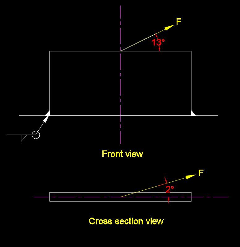
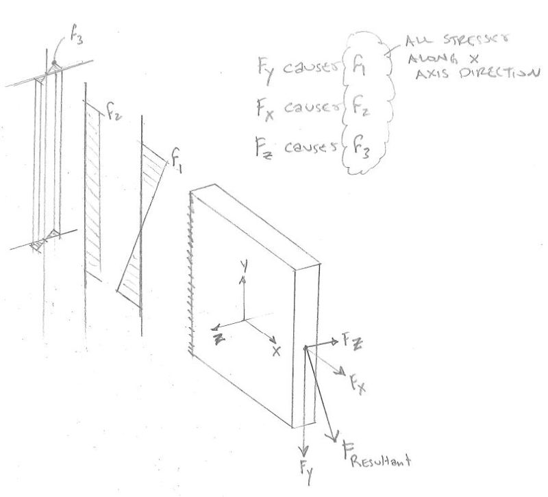
I am checking stresses on a rectangular plate (SA-516-70) results from an external load. below is a summary of what I have:
1) Maximum strong axis bending stress is fbx = 15,964 psi, allowable strong axis bending stress= Fbx =0.6 x Fy = 22,800 psi.
2) maximum weak axis bending stress is fby = 5,745 psi, allowable weak axis bending stress = Fby = 0.75 x Fy = 28,500 psi ( the section is compact per AISC 9th edition).
3) Tensile stress = fa= 740 psi (allowable tension = Ft = 0.6 x Fy = 22,800)
now can I say the design is acceptable because:
1) fbx < Fbx
2) fby < Fby
3) fa < Ft
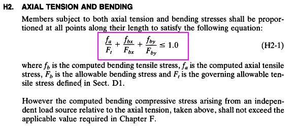
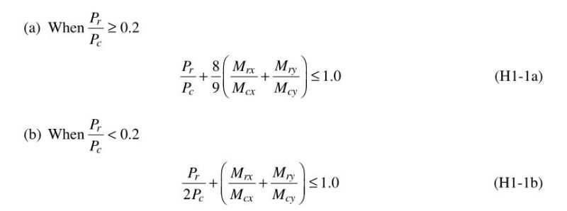
4) fa/ Ft + fbx/Fbx + fby/Fby= 0.93 ≤ 1.0
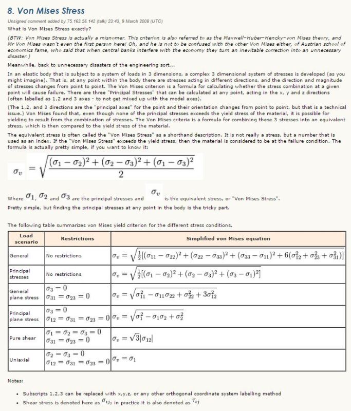
or I have to find the combined bending stress to check that too separately. if yes, what will be the combined stress and its allowable, will it be √(fbx2 + fby2)= 16,966 or just by adding up fbx + fby = 21,709

Thanks in advance,
Regards,
 
Replies continue below

Recommended for you

are the three loads (2 axes bending and axial) imposed at the same time ?

another day in paradise, or is paradise one day closer ?
 
Do a search for von Mises stress.
There are numerous theories of failure out there - we tend to use von Mises for steel subjected to multiple stresses.

You don't simply add fbx and fby together.

A short summary found here (under item 8): Here's the snippet:
Short_von_Mises_summary_ylm3o0.jpg


Check out Eng-Tips Forum's Policies here:
faq731-376
 
really ? the three loads all produce normal stresses on the section and should be superimposable. You can't superimpose as you have different allowables for the three loads.

if you're combining the three loads just to envelop all possible conditions then I'd go with 4).

combined bending stresses should simply add (not vector sum).

another day in paradise, or is paradise one day closer ?
 
Thanks for replies:
yes the three stresses are imposed at the same time but there is only one load applied on the plate. (load has lateral angle so produces weak axis bending too)
I am checking stresses per AISC 9th edition chapter H, combined stresses, (H2. AXIAL TENSION AND BENDING) and equation H2-1 which is fa/Ft + fbx/Fbx + fby/Fby ≤ 1.0

1_xjspcm.jpg
 
that'd be the way to go ...

another day in paradise, or is paradise one day closer ?
 
so there is no need to simply add strong and weak axis bending stresses (or do a vector summation) and check that too? I should be checking it as below:
1) fbx < Fbx
2) fby < Fby
3) fa < Ft
4) fa/ Ft + fbx/Fbx + fby/Fby ≤ 1.0

Thanks
 
That is what I'd generally do.

There's no vector summation or von mises excitement (assuming shear is minimal), because your stresses are all in one direction (along the length of the plate). Your max stress is just the corner where the tensile load and two bending maximums overlap, so you basically just need to add them together.

You've effectively done that, but you've accounted for the variance in allowables by summing proportion of capacity instead of pure stresses. If the allowables were the same, your summation would be mathematically equivalent to (fa+fbx+fby)/allowable.
 
@ JAE, Von Mises criterion is about three principal stresses i.e max normal stress, minimum normal stress and shear stress, right? here I have one tensile stress, one strong axis bending stress but the third one is weak axis bending stress and they all produced by one single load, do you believe that Von Mises resultant stress formula can be true in my case too?

Thanks
 
Maybe I'm not fully understanding your situation - if the fb values (both x and y) produce stresses in the same direction then yes, you can add them as is suggested above.

But if you have one fb stress in one direction and the other fb stress orthogonal to it, you don't simply add them together.

I was envisioning your situation as a plate in "two-way bending" where a flat plate deflects into a bowl-like shape. Thus the bending stresses are perpendicular and there are shear stresses within the plate as well...thus von Mises stress considerations.

However, if you mean, by the terms "strong axis" and "weak axis" something more like a beam being bent in two ways, and you are looking at stresses that are both parallel to each other then add away or use the interaction equation you've suggested above.

Check out Eng-Tips Forum's Policies here:
faq731-376
 
You might want to double-check the allowable bending stress (Fb) for the strong-axis bending case. Depending on the combination of unbraced length, depth of the plate, and plate thickness, the allowable bending stress could be much less than 0.6Fy.
 
Thanks everyone for sharing your thoughts, below is a snapshot of what I have. the shear stress is very small almost 20% of its allowable (I know if the shear stress is less than 60% of shear allowable stress then it can be ignored). so basically I have strong axis bending moment, weak axis bending moment and tension on a cross section at the very bottom of the plate.

@ winelandv, Regarding allowable bending stress at strong axis, per AISC should be (0.6 to 0.75) x Fy, so I am using the minimum allowable. am I not correct?
I am a pressure vessel engineer (mechanical engineer) and not expert in AISC standards. this is a part of lifting lug design


2_vpwfgb.jpg
 
OK - so based on your posted graphic this is not necessarily a von Mises but you might do as you suggest:
fa/ Ft + fbx/Fbx + fby/Fby ≤ 1.0

However, AISC currently has a different interaction equation:
AISC_Ch_H_Interaction_q4gvjn.jpg


The whole AISC spec can be found (free) here: Look in Chapter H in section H1.


Check out Eng-Tips Forum's Policies here:
faq731-376
 
MO82, I tend to use the ASME BTH-1 (Design of Below-the-Hook Lifting Devices) for any padeyes/lifting lugs that I design. A lifting lug directly attached to the vessel is technically outside of the scope, but it has many failure state checks for pin connections (such as a shackle in a lifting lug) that don't show up for bolted connections:

- tensile strength through the pinhole accounting for a pin/hole diameter ratios less than .9 (as usually happens with a shackle in the hole)
- single plane fracture strength
- double plane shear strength

At any rate, for the combined stress check, JAE has set you on the right path (though AISC has changed to a strength basis instead of stress for all their design equations).

Have fun designing your lug!
 
Just like winelandv we use the BTH-1 spec for lugs also.

Check out Eng-Tips Forum's Policies here:
faq731-376
 
@ JAE, I am aware that current AISC has different equations I rather to use the old equation since it looks much simpler to me than new equations. I think I should be fine using the old one as new AISC states "User Note: Section H2 is permitted to be used in lieu of the provisions of this section." which H2-1 has exact same old equation. the only thing I don't fully understand is why are we're adding strong bending stress and weak axis bending stress when in fact they are not in same directions. (they are perpendicular)

@ winelandv, Thanks for your input, I am aware of other design requirements of shear, bearing stresses at pin hole and the rest and I am checking them too.
 
the bending moments are in different directions but the stresses on the section are the same (tension/compression).

another day in paradise, or is paradise one day closer ?
 
Per rb1957:
rb1957_qqbyli.jpg


Check out Eng-Tips Forum's Policies here:
faq731-376
 
Status
Not open for further replies.

Part and Inventory Search

Sponsor