Eng-Tips is the largest engineering community on the Internet

Intelligent Work Forums for Engineering Professionals

Common Datum with eccentric axis' to control orientation of flats. GD&T

Status
Not open for further replies.

RevSol

Mechanical
Feb 3, 2024
3
0
0
US
Howdy all.

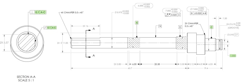
Would the following work to control the orientation of these flats to the 2 axial datums that are offset?

If I have datum A establishing 1 axis, datum C (eccentric portion) establishing the other axis.

Then referencing A-C as a common datum to establish clocking of the shaft and then use parallelism and perpendicularity to control the flats?

Or is there a better, cleaner, easier way? I need to know how to best clock this part to the eccentric portion.

Thanks!!!
ss_inmcpt.jpg
 
Replies continue below

Recommended for you

I suppose adding a diameter symbol for the [A] and datum features will happen later?

Instead of Perpendicularity and Parallelism, use Angularity which is less biased in interpretation.
 
What would I reference as the datum for the angle callouts for the flats?

and... how would I reference the... zero angle for the vertical flat?

Just sort of stuck on how to create the callout that compares the flats to the eccentric portion.

 
I also think it would be better to use [A-B|C] so that there is a better orientation control.

You don't need any angle values, 0 degrees and 90 degrees are default, but if you like, the top surface in that view is at [90 degrees] to the plane of the datum references and the front surface is at [90 degrees] to the top surface.
 
So, just to be clear, there could never be a combination of the two eccentric axis’ like that to form a common datum, in this case A-C? Is that type of combo even possible? Would that make a plane?


Where can I read more about these defaults?

Is that an ISO thing?

 
You can, but the features are very small and small variations will yield large error chances when magnified by the distance to the features being controlled. [A-C] does make a chitty basis for making the measurement. [A-B|C] makes a far better one. If you want a chitty basis you can use it.

Is there some reason you object to using what seems like the combination of surfaces that will control the orientation of that shaft?

Buy a copy of ASME Y14.5. It's around $250 and has answers about the angles and many more.
 
The way to tell if a scheme is stable is to see if that would be a good way to hold the part still while machining the feature that is being controlled.

Would a machinist put [A] in a v-block and [C] in a separate v-block and expect those to withstand the machining forces?

You already used [A-B] to control the feature used for [C] because [A] is hardly stable enough on it's own.

I would likely have set features used for [A] and to both be controlled by total runout to [A-B].
 
I agree with the angularity recommendation.
Parallelism and perpendicularity are also not wrong in your case but I would recommend using them only in simpler cases where the primary datum is a plane tangent to a planar surface or the axis of a circumscribed/inscribed cylinder. Maybe the axis of a cone too. Your A-C common datum is just a bit more complex than that, so angularity is a good way to control orientation relative to the datum reference frame without making anyone think too hard what exactly the feature needs to be parallel or perpendicular to.
 
Status
Not open for further replies.
Back
Top