Eng-Tips is the largest engineering community on the Internet

Intelligent Work Forums for Engineering Professionals

Composite positional tolerances with fixed/floating fastener formula.

Status
Not open for further replies.

AmberAardvark

Mechanical
Jul 8, 2021
1
0
0
GB
Hi All.

This is my first post so hope it is all correct.

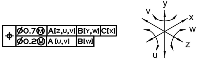
I have some prints to check where the engineer has used composite tolerancing for some hole patterns, they seem to be very my just plug and play values for the hole clearance from the CAD software. On preforming the fixed and floating fastener formula which segment should be considered in the formula the upper which constrains location and orientation of the pattern, or the lower which constrains the location and orientation of individual holes within the pattern?

The more my head spins, I keep coming back to the lower segment as this controls the holes pattern to each other.

Any advise is welcomed, thanks.
 
Replies continue below

Recommended for you

AmberAardvark,

I usually use composite tolerances on things like sheet metal, where the fabricator can punch out an accurate pattern, but they cannot locate it accurately from a bend. In most cases, I have a composite requirement, where I need fastener holes to line up, but I am way less concerned about the location of the mounted part.

The positional tolerance with respect to datum features[ ]A, B and[ ]C, locate the mounted part, probably sloppily.

The positional tolerance with respect to your primary datum feature, lines the holes up with the holes on your mounted part. This is where you worry about floating and fixed fasteners.

Normally, I would call up a composite tolerance because there is an opportunity to tolerance some sloppiness, and I want the reduced cost.

--
JHG
 
It depends on how the two parts are located to each other in assembly. Do the fasteners locate them to each other (as in parts that do not need accurate location to each other) or are the datum features from the upper segment of the Feature Control Frame doing that? If the latter, the tighter tolerance in the lower segment won't help to prevent failure to assemble. If the patterns in the two parts shift in opposite directions relative to the interface features per the upper segment tolerance specified larger than the fixed fastener formula provides, the parts won't fit.
 
the fixed and floating fastener formula which segment should be considered

For most of the composite position tolerance, the location of the holes pattern are not important to the DRF but the holes will be tightly controlled to each other for the mating fasteners or rivets, and for some cases it is also important the holes need to be well oriented (parallel or perpendicular) to the DRF.
Based on the above understanding, the upper segment position tolerance will be large, and the lower segment tolerance will be held tight for the fasteners or rivets to fit, so the fixed and the floating fastener formula will be used on the lower segment to calculate the tolerance.

the upper which constrains location and orientation of the pattern, or the lower which constrains the location and orientation of individual holes within the pattern?

The upper segment constrains the translational and rotational DOF for the pattern of features to the specified DRF, but the lower segment only constrains the rotational DOF. The figure below is an idea for your reference, please note there is no translational DOF (X,Y,Z) on the lower segment.
GD_T_Forum_fzhcy8.jpg


Season
 
Status
Not open for further replies.
Back
Top