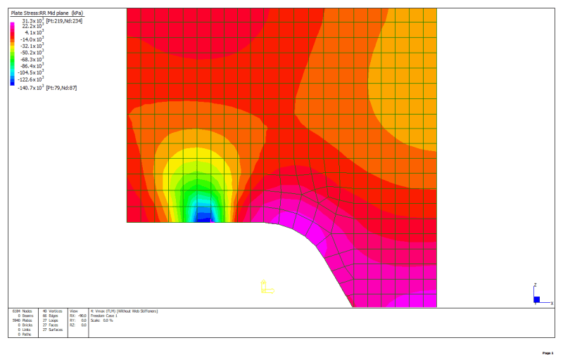
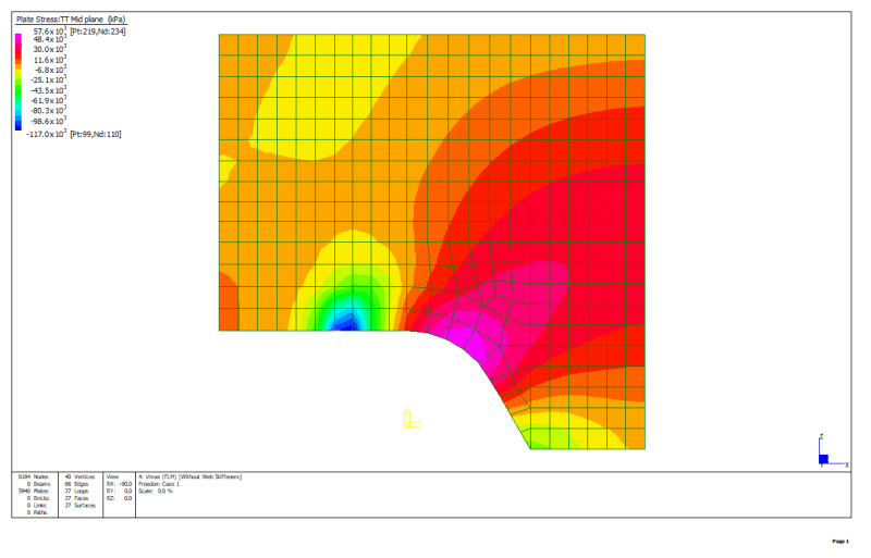
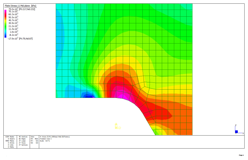
Hello,
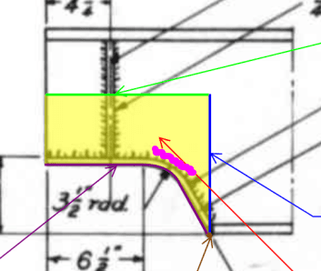
We are assisting the council with the rehabilitation of a ~80-year-old steel bridge. They have identified corrosion to one of the roadway stringer beams. The corrosion has resulted in substantial but localised steel thickness loss to the lower web and flange. The stringer beams are simply supported by the cross girders and composite with the roadway slab. The corrosion is located at the end of the beam where the web is coped. It is proposed to replace the affected section of web and flange as shown in the diagram below. The lower flange would be pre-welded to the web section in the shop leaving only the upper horizontal web weld, vertical web weld and flange weld to be performed onsite. All welds to be full penetration butt welds performed from both sides.
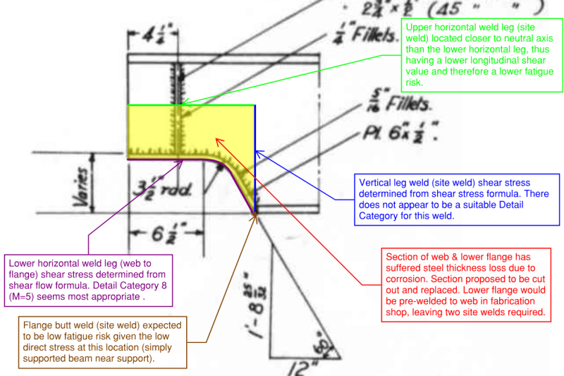
Below are my questions:
[ul]
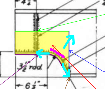
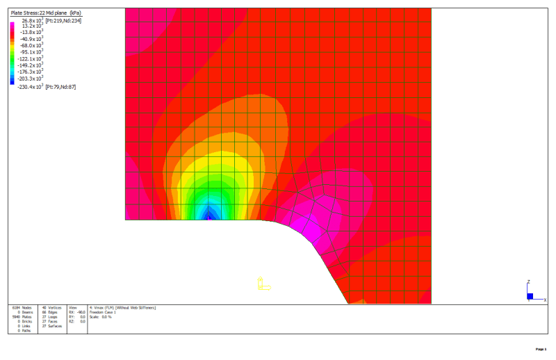
[li]Would anyone be able to sugguest a suitable Fatigue Detail Category for the vertical leg weld (blue in above diagram)? Given the proximity to the support, the only tangible action at this location is vertical shear stress.[/li]
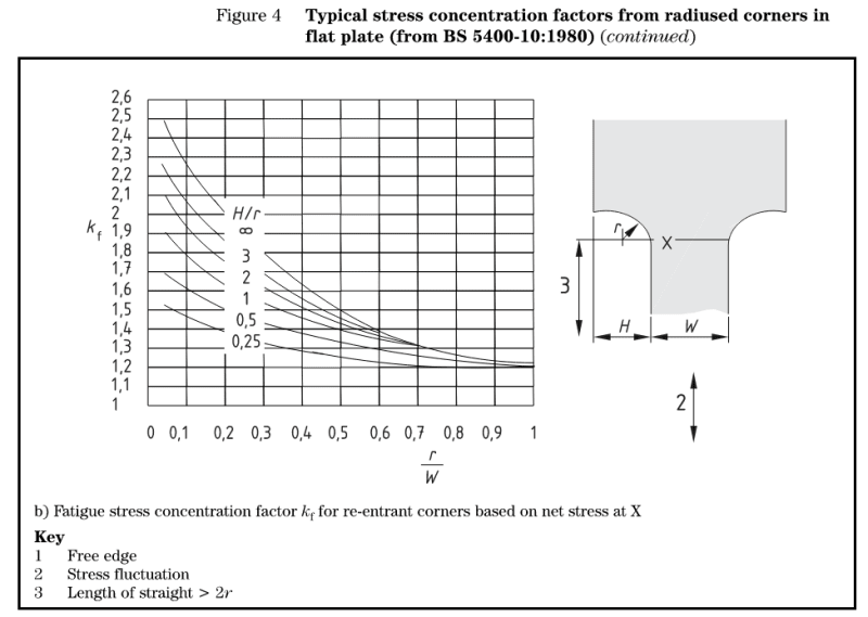
[li]Is Fatigue Detail Category 80 (as per below) the most suitable for lower horizontal leg (purple in above diagram)?[/li]
[li]Are my assumptions for the remaining welds in the above diagram reasonable?[/li]
[/ul]

Thanks!
We are assisting the council with the rehabilitation of a ~80-year-old steel bridge. They have identified corrosion to one of the roadway stringer beams. The corrosion has resulted in substantial but localised steel thickness loss to the lower web and flange. The stringer beams are simply supported by the cross girders and composite with the roadway slab. The corrosion is located at the end of the beam where the web is coped. It is proposed to replace the affected section of web and flange as shown in the diagram below. The lower flange would be pre-welded to the web section in the shop leaving only the upper horizontal web weld, vertical web weld and flange weld to be performed onsite. All welds to be full penetration butt welds performed from both sides.

Below are my questions:
[ul]
[li]Would anyone be able to sugguest a suitable Fatigue Detail Category for the vertical leg weld (blue in above diagram)? Given the proximity to the support, the only tangible action at this location is vertical shear stress.[/li]
[li]Is Fatigue Detail Category 80 (as per below) the most suitable for lower horizontal leg (purple in above diagram)?[/li]
[li]Are my assumptions for the remaining welds in the above diagram reasonable?[/li]
[/ul]

Thanks!

