Continue to Site

Eng-Tips is the largest engineering community on the Internet

Intelligent Work Forums for Engineering Professionals

  • Congratulations waross on being selected by the Eng-Tips community for having the most helpful posts in the forums last week. Way to Go!

Composite Wood Column Fails Horizontal Shear 2

Status
Not open for further replies.

SteveGregory

Structural
Jul 18, 2006
554
I have a continuous timber frame column with knee braces at 2 levels. At the lower level, the bending in the column results in a horizontal shear stress overload. I have maxed out the wood sizes available to me. So I came up with an idea to reinforce the column for shear by adding steel bolts across the neutral axis of the column to take the excess shear. Am I crazy? Do my calculations make sense?

I have attached 1 sheet of hand calcs with moment and shear diagrams and the column section used. The wood is Select Structural Doug Fir. The 2nd Floor Beam has a high tensile load on the column and the knee brace below has a high compressive load on the column. I will be slipping a 1/4" plate between the outer plies of the column and the heavy timber and using a number of 3/4" bolts to attach the beam and brace to the column.
 
 https://files.engineering.com/getfile.aspx?folder=839abea7-454e-40a4-9d7e-17a9bf8b0dea&file=img001.pdf
Replies continue below

Recommended for you

Are these forces due to D+L or is it wind?

Any shot at making your floor joists deeper to reduce the moment at the column?

What sections are you using on the knee braces?

I would think putting a bolt through the column would do nothing since a bolt is not continuous.
 
The maximum forces in the column and knee brace are for D+L, no wind in this combination.

The floor beam is made up with 4-2x12's (2-2x12's + 7.5" space + 2-2x12's)and the knee brace is a 6x8 to fit in the 7.5" space.

The bolts through the column timber are perpendicular and pass through the neutral axis of the column. The idea is the bolts cross the horizontal shear plane to pick up the shear that the wood can't handle. This is somewhat analogous to shear studs connecting a steel beam to a concrete slab to make a composite section. The difference here is the wood has a relatively weak horizontal plane (neutral axis) that gets reinforced with bolts. The bolts connect the two "halves" of the column defined by the neutral axis.
 
I don't think using bolts as some kind of shear reinforcement - like stirrups in a concrete beam - is valid - I could be wrong but I've never seen anything about that.

Also - Douglas Fir Larch Sel. Structural - Fv' = 1.6 x 180 = 288 psi in the 2015 NDS for load combinations with wind.


Check out Eng-Tips Forum's Policies here:
faq731-376
 
I used to do timber frames but have given up on them as the connections always seemed too sketchy to me. If you have enough load in the knee brace to cause a shear issue, how are you tying the column back into the horizontal beams? The loads must be huge.
 
XR, you are correct. The tension force on the column from the 2nd floor beam is 24.4k. I will be slipping some 1/4" plates between the timber and the outer plies and adding a bunch of bolts. I am not sure about which segment of the column to reinforce, A. 1/2 above and 1/2 below the 40" section of constant shear, B. in the 40" section of constant shear, C. 1/2 above and 1/2 below the the maximum moment (knee brace connection).

JAE,Loads shown are dead and live only, no wind. I have never seen wood being reinforced for horizontal shear other that by up-sizing a beam. That's why I posted in this forum. Horizontal shear is almost never a problem. Fv for timbers 5x5 and larger (Table 4D) is 170 psi.
 
Are you saying that by drilling holes perpendicular to the neutral axis and putting bolt through it, you are in turn reducing the stress? I know a hole is a good way to mitigate crack propagation but I am unsure if that would work for wood, and to what end? Assuming you were planning to use a large washer, I imagine the wood bowing out between the bolted locations or doing something else odd and hard to predict.

If you are limited on section sizes, would it not make more sense to lag bolt the 2x12s to the short sides of the 8x14s to form an I-beam? Just miter your knee brace and terminate into the side of the interior 2x12.
 
Do you need the braces for lateral stability or are you using the wall sheathing for that? If not, get rid of them and your shear problem goes away as long as the horizontal beam can span between columns.
 
Good thought! These frames are 10' on center and no real wall sheathing at the ends. We have commercial space on the first floor and apartment living above.
 
Yep - you are right - I should have referred to 4D and not 4A.
Just assumed wind with the knee braces so the 1.6 DLF can't be used.


Check out Eng-Tips Forum's Policies here:
faq731-376
 
I don’t see what the bolts would do in that situation. Since You are at the maximum member size, is there no way you can increase the shear area by making a built-up cross-section?
 
To answer the question about the purpose or function of the bolts:
When a wood beam is overloaded in shear, the beam will split horizontally through the neutral axis. In a rectangular section, this occurs at the center. The lateral longitudinal force in each half of the beam is called the "horizontal shear" force. When the beam splits horizontally, you now have 2 beams, one resting on top of another.

If we were bolting two separate pieces of wood together in a tension connection, the bolts would be loaded in single shear. The tension is each member is equal and in the opposite direction. In this case, the "tension" or horizontal shear is partially resisted by the wood fibers up to 170 psi. The remaining lateral force on each side of the neutral axis is resisted by the bolts in single shear that prevents the beam from splitting into two halves.

My original post was asking the question, can the steel bolts share the load with the wood fibers along the neutral axis to resist horizontal shear? the next question, can the number of bolts required be determined as shown in my calculations?

I hope this clarifies everything. Thanks everyone for your comments and suggestions so far.
 
I see. Certainly a bolt would assist in keeping the "plies" together but I am not sure that it would keep it from splitting in the first place. This is a very interesting concept. Do you have real world examples on this?

If you were to set up a test with a two simply supported beams. One with the proposed perpendicular bolts @ 12" O.C. and one without and both subject to the same loading. My hypothesis remains that the beam without the holes will be more resilient. I could be horribly wrong. If your theory is true, then I would think an interference fit on the bolt would be good here.

My inclination remains to build up an "i-beam" using the 8x14 as the web and the 2x12s and flanges.

 
mreg,
The 8x14 and 2x12's can't be rotated. My calc sheet shows the orientation of the beam-column, the N.A. (neutral axis) and the bolt through the 8x14 only. The 7.5" width of the 6x8 knee brace lines up with the 7.5" width of the 8x14. The bolts do not hold the 2x12's to the 8x14 - see calcs from original post.

I am hoping someone in the forum, can show me why it won't work or perhaps why it will work or suggest another solution that will work.

 
If you treat the member as two separate members one half the depth of the current member do you get more shear capacity?
 
SteveGregory said:
I am hoping someone in the forum, can show me why it won't work or perhaps why it will work or suggest another solution that will work.

It won't work, or perhaps will work poorly, because:

- Given slip etc, you'll have to fail the wood in shear before engaging the bolts. So it really the capacity of the wood or the bolts but not both acting in concert.

- Again because of slip, by the time that you'd fully engage the bolts, I'd expect this part of the your structure to be in ruin.

Wood members can and are reinforced using modern wood screw technology, typically installed at an angle. Stuff like this: Link. I think they even have some decent youtube vids on shear reinforcement. So there's that. In this particular instance, however, my feel is that you should interpret your difficulties as indicating that this is simply not a great system to begin with. To make knee bracing calc out for systems with any serious gravity loading, you've really got to:

1) Make the beam very stiff in comparison.

2) Make some "convenient" assumptions about what loads the knee bracing does and doesn't see.

3) Give some careful consideration to where joints slip in the system might relive some of the troublesome stress.

What is your end game with the knee bracing. Is it intended to be part of the lateral system? Also, what does your beam to column joint look like?


I like to debate structural engineering theory -- a lot. If I challenge you on something, know that I'm doing so because I respect your opinion enough to either change it or adopt it.
 
Koot,
I think you are right about the slip or yielding before the bolts are fully engaged. Maybe the screw idea would work. If this was a composite steel/concrete beam, I would place equal number of studs on each side of the maximum moment at the knee brace location. Does this sound right for reinforcing the wood also?

As for the knee braces, they are intended to cut down the span of the floor beams and give lateral stiffness to the frame. The frames are roughly 36' wide and spaced at 10' on center.
 
SteveGregory said:
I would place equal number of studs on each side of the maximum moment at the knee brace location. Does this sound right for reinforcing the wood also?

Seems to me you probably don't need anything on the low shear size of the moment peak. The wood itself can probably get that job done.

SteveGregory said:
they are intended to cut down the span of the floor beams

That can be a tough row to hoe.

I like to debate structural engineering theory -- a lot. If I challenge you on something, know that I'm doing so because I respect your opinion enough to either change it or adopt it.
 
Could you just use a glulam column instead of dealing with this reinforcing business? A 24F-V8 DF glulam has a shear capacity of 265 psi which would meet your requirements. I feel like these level of loads require some sort of engineered lumber. A PSL column would work also.
 
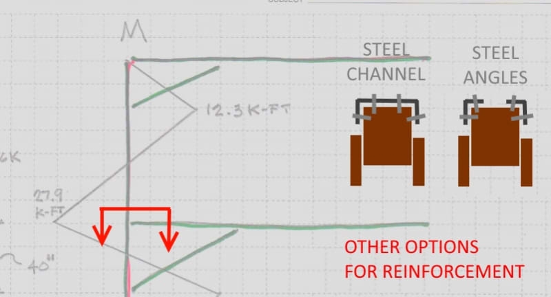
What about just reinforcing what you have? Do you think something like this would be acceptable visually?

COLUMN_REINF_pzrkbn.jpg
 
Status
Not open for further replies.

Part and Inventory Search

Sponsor