hotmailbox
Structural
- Dec 2, 2006
- 90
I tried to search the forum any posts regarding Simpson ATS, Mitek Z4 system but I couldn't find any that is close to what I want to discuss. I know I should have posted in Shearwall design forum but it seems like most traffic is in this forum so I am ok if this one is moved back to Shearwall forum.
I used to use or specify either Simpson ATS or Z4 (if requested by contractor for cost savings or preferences) like 13-14 years ago using Simpson ATS specifier software which is not available anymore. Back then, the tie-down system I detailed or on Simpson DWGs was symmetric assembly (number of posts/studs is the same on each side of rod). I can clearly see the advantage of asymmetric post/stud pack where you can gain more moment arm to reduce tension but I am still not so sure to justify that the smaller pack won't buckle first or how the compression force is distributed based on the axial stiffness of the pack below. Anyone has any paper or test results supporting this configuration?
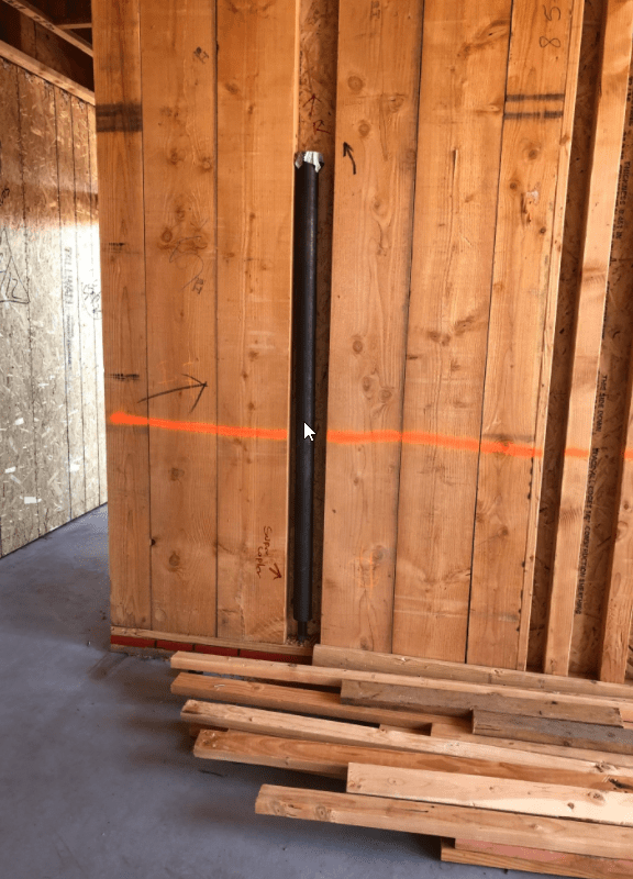
The second thing I want to discuss is that since the 4" wall is so thin, the compression capacity of any post/stud is very small leading to some crazy assembly like the one below that needs to resist 65 kips in tension/compression at the bottom level (not my job - from a sample project by Z4). If this 6" wall, I can replace (8)4x6 posts by (6)2x6 (making total of (9)2x6 that can resist 9*7.25kips per stud with Cd = 1.6 and ignoring out-of-plane forces). This is the reason I always want to use 6" wall for multi-story shear walls (3 and up). Fortunately something like this typically occurs at demising walls (double 4" walls with gap) so you won't see kitchen vent ducts coming through at the end area of the wall but obviously they have to have fur wall in order to install electrical boxes, switches.... What is your take in this regard?
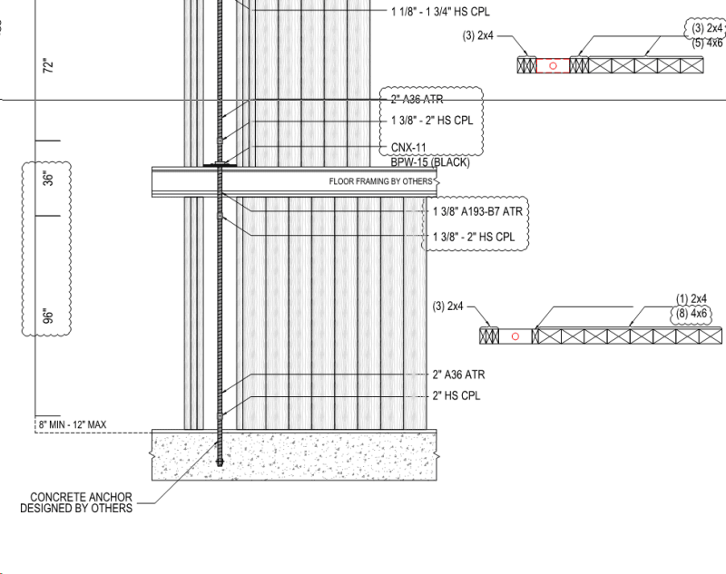
Looking at the stud pack above, you can clearly see that the distance between the tension rod and the center of the compression block is greatly smaller than what you assume or input in the spreadsheet or Woodworks Shearwall program. I typically set 12" to 18" in Woodworks Shearwall settings for tie-down system then obviously I underestimate the tension demand of the ATS system if I get something like this. So how do you tackle this issue in your practice? Iterative design?
I used to use or specify either Simpson ATS or Z4 (if requested by contractor for cost savings or preferences) like 13-14 years ago using Simpson ATS specifier software which is not available anymore. Back then, the tie-down system I detailed or on Simpson DWGs was symmetric assembly (number of posts/studs is the same on each side of rod). I can clearly see the advantage of asymmetric post/stud pack where you can gain more moment arm to reduce tension but I am still not so sure to justify that the smaller pack won't buckle first or how the compression force is distributed based on the axial stiffness of the pack below. Anyone has any paper or test results supporting this configuration?
The second thing I want to discuss is that since the 4" wall is so thin, the compression capacity of any post/stud is very small leading to some crazy assembly like the one below that needs to resist 65 kips in tension/compression at the bottom level (not my job - from a sample project by Z4). If this 6" wall, I can replace (8)4x6 posts by (6)2x6 (making total of (9)2x6 that can resist 9*7.25kips per stud with Cd = 1.6 and ignoring out-of-plane forces). This is the reason I always want to use 6" wall for multi-story shear walls (3 and up). Fortunately something like this typically occurs at demising walls (double 4" walls with gap) so you won't see kitchen vent ducts coming through at the end area of the wall but obviously they have to have fur wall in order to install electrical boxes, switches.... What is your take in this regard?
Looking at the stud pack above, you can clearly see that the distance between the tension rod and the center of the compression block is greatly smaller than what you assume or input in the spreadsheet or Woodworks Shearwall program. I typically set 12" to 18" in Woodworks Shearwall settings for tie-down system then obviously I underestimate the tension demand of the ATS system if I get something like this. So how do you tackle this issue in your practice? Iterative design?