hugary1999
Mechanical
Suppose I have a 3D beam and I wanna apply a tip load as shown in the figure below:
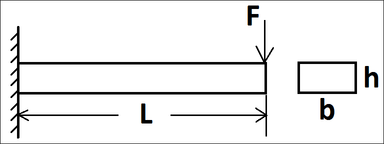
I want to apply the tip load on the middle of the top edge.
The 3D simulation results look good. Below is the deformation graph:
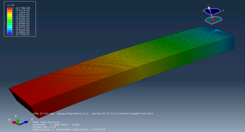
Now I want to model it in 2D as a wire:
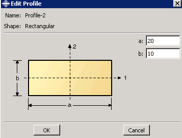
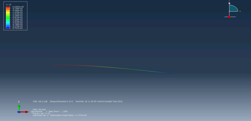
However, I can only apply the tip load on one end of the wire, and I cannot specify the location of the tip load (i.e. middle of the top edge).
I plotted the axial stress along the wire by creating a path of edge list:
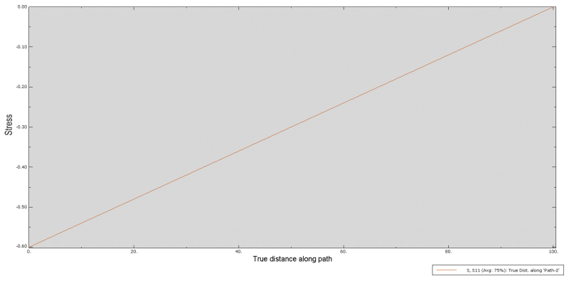
The values agree with my theoretical solution.
Since the axial stress is negative, so I guess by default Abaqus looks at the bottom edge?
If I am understanding it correctly, the axial stress should be zero at neutral axis, positive above NA, negative below NA.
My questions are:
1. Can I specify the tip load location?
2. Is there a way I can plot the axial stress of the top edge or neutral axis?
I want to apply the tip load on the middle of the top edge.
The 3D simulation results look good. Below is the deformation graph:
Now I want to model it in 2D as a wire:
However, I can only apply the tip load on one end of the wire, and I cannot specify the location of the tip load (i.e. middle of the top edge).
I plotted the axial stress along the wire by creating a path of edge list:
The values agree with my theoretical solution.
Since the axial stress is negative, so I guess by default Abaqus looks at the bottom edge?
If I am understanding it correctly, the axial stress should be zero at neutral axis, positive above NA, negative below NA.
My questions are:
1. Can I specify the tip load location?
2. Is there a way I can plot the axial stress of the top edge or neutral axis?