Eng-Tips is the largest engineering community on the Internet

Intelligent Work Forums for Engineering Professionals

Concentric to Lap Winding Conversion 4

Status
Not open for further replies.

EngRepair

Electrical
Oct 13, 2012
49
0
0
HR
Several examples from a publication on how to convert a three-phase concentric winding to a double-layer lap winding are found online.
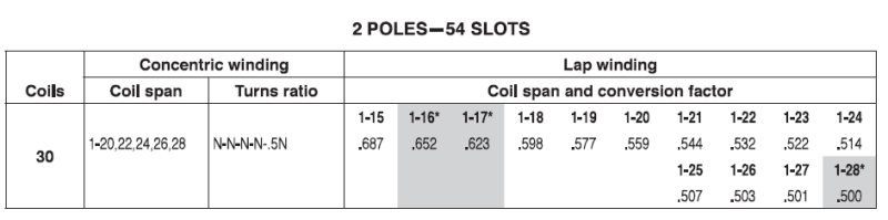
The displayed table shows the value of the conversion factor in the case of a 54-slot, 2-pole, mixed winding ( 30 coils in total) with pitches of 1-20, 22, 24, 26, 28, and turns ratios of N, N, N, N, 0.5N, respectively.
On the right side of the table, conversion factors to lap winding are shown for various winding pitches from 1-15 to 1-28.
The number of turns per phase of the new winding is obtained by multiplying the number of turns per phase of the original winding by a correction factor. PROBABLY. I am not sure.
However, I've attempted to calculate these correction factors, but I couldn't obtain the values shown.
At first glance, it seems to me that the values of all the correction factors in this example must be greater than or equal to 1. Or I am missing something?
Is there anyone who can explain this and confirm if the displayed table is correct?

ovo_oxk0st.png
 
Replies continue below

Recommended for you

I'm probably not the best guy to weigh on this since I know very little about concentric windings (probably edison and others can give better advice). I'll give my simplistic take fwiw

I think most concentric windings are a single layer winding (while lap is a 2 layer winding). In that case a concentric winding has half as many coils as a 2-layer lap windng in the same core. So from that standpoint it makes sense that we would expect approximately (*) half as many turns per coil (factor 0.5 in the table) multiplied by twice the number of coils in order to give the same total turns.

(*) Then we have to account for difference in spans. I'm not sure exactly how to apply that to explain these particular table entries. Interesting that the entry 1-28 comes out with exactly 0.500 which seems like a clue, but I can't explain why that would be an exact representative comparison.

I could be way off base...
 
Pitch factor is never more than 1 (sin 90 deg).

Concentrics are mostly single layer and hence fewer coils with more turns and lap winding is mostly double layer and hence more coils with fewer turns.

If N=10 in concentric, then chose a lap pitch that will give you the nearest whole number, i.e. 1-18 = 6 turns app.

For N=8, 1-17 = 5 turns app

You need to maintain original connection (series or parallel connection).

Muthu
 

It is clear how to obtain the conversion factor in the mentioned case, although it is not clear how this could be useful to the average winder. The table appears to be quite confusing, and it is easy to make a mistake when using it.
Furthermore, there is a big question mark regarding the outcome of the conversion, which is not mentioned at all.
In summary:
The winding factor of the original winding with 30 coils (see the table on the left) is 0.955469. The winding factor of the replacement lap winding ( on the right), for example for pitch 1-15, is 0.695. The ratio of these two numbers is 1.3741.
The original winding has 10 coils per phase, or a total of 9N turns per phase (N is the number of turns per full slot coil).
The new winding will have 9N * 1.3741 = 12.36N turns per phase. Since the new winding is a double-layer lap winding, one phase will have 18 coils, and the number of turns per coil will be 12.36N/18 = 0.687N.
And that's it. I hope it's clear.
Regarding the outcome of the conversion, the table lacks the main information, which is: whether and by how much the motor's power will change after the conversion. This is a matter for another discussion, but I believe it is entirely irresponsible to "help" the winder make such a conversion without knowing how much the motor's power (torque) will decrease (in this case) or will increase.
Our approach to this conversion is completely different and includes other types of conversions (not just concentric to lap or vice versa). We simply observe both windings as a whole, compare their winding factors, but not only that. It is necessary to compare the content of harmful harmonics in both windings and, most importantly, determine how much the power will change when the converted winding is used.

ACW Winding Redesign
 
The conversion factor pretty much gives the same turns per phase in both windings. Hence, no change in flux density and speed. So I don't see any torque or HP changes.

I have done a few (and rare since these types of concentric windings are) such conversions with zero problems.

Muthu
 
Hi, edison123,
Mentioned pitch of lap winding is 1-15 ( as an example, not 1-18), and the conversion factor from the table is 0.687.
You are avoiding addressing this case and bringing up a new case with a pitch of 1-18, which, by the way, you also haven't calculated accurately.
Something has slipped through in your procedure. You need to be precise. Start with both winding factors (not just one) and the conversion factor from the table.
Let's first solve the first example before moving on to the second.
Note that 9N and 12,36N is enormous difference. Number of turns per slot before and after is 1N and 2*0,687N = 1,374N.
That means you need to reduce cross-sectional area of conductor 1,37 times which is more then zero problem. The same HP???
I'm not saying that the conversion factors in the table are calculated incorrectly, but that the whole redesign is senseless and ultimately leads to a faulty motor, as well as wasted material and time spent.
More on Winding Efficiency
 
Hi zlatkodo

May be you should re-read what I wrote, my math and the table. Even accounting for winding factors, the concentric winding would give 86 turns per phase (you can do the math) which is just as close to 90 turns in lap winding.

And may be you could also explain how a double layer lap winding would have more no. of turns per coil than the single layer winding for the same voltage and speed.

And the above table cited by OP is from EASA, a reliable source, don't you agree?

Muthu
 
I have already explained in previous comments in great detail the step-by-step procedure used to calculate the conversion factor.
I am confident that it is clear to anyone who can and wants to understand it. Therefore, there is no reason for me to repeat it all.
edison123 said:
you could also explain how a double layer lap winding would have more no. of turns per coil than the single layer winding
Such a question surprised and saddened me because I did not expect it from you.I don't know what to tell you. I would have expected such a question from a some beginner.
Regarding the source of table, I do not know who created the table, and to be honest, I don’t care it at all. I am only interested in raw facts that can be checked and proven.
A message to all others who are unsure about their particular redesign: please feel free to contact us for technical support.
Contact us
 
Please don't hide behind EASA. Express yourself.
I've already expressed my thoughts on the table.
It's simply a proper mathematical tool (a simple calculator) designed to assist the winder in selecting the conversion option, i.e., making his own decision about which option is best for his specific case. If he is capable of doing so. If he is not, he should seek support ( see the link above).
edison12345 said:
how a double layer lap winding would have more no. of turns per coil than the single layer winding
Congratulations. For this gem, I'm giving you one more star.
ACW
 
Moving past the distraction, question to OP.

Is your concentric winding configuration same as given by you in your first post?

54-slot, 2-pole, mixed winding ( 30 coils in total) with pitches of 1-20, 22, 24, 26, 28, and turns ratios of N, N, N, N, 0.5N, respectively.

If yes, what is N? (which should be an even number).

Muthu
 
In general my view is tables are much more useful if you can show an example to recreate where the number came from. LPS to zlatkodo for his input on that.

 
Dear all,
Converting to lap this concentric winding will have very few reasonable options available, rougly speaking about the AC motor redesign the key is to keep the magnetic densities in the airgap, back iron, and tooth in +/- 2 %. Normally the main guidance is the airgap density that varies (at the same connection) directly with the flux per pole but the flux per pole varies inversely to (turns x chord factor), thus it is possible to have more turns in the slot if the chord factor decreases. Because the chord factor depends on the teeth spaned or span (pitch -1), slots, and poles thus lower the pitch lower the CF.

CF = Sin (90 x (teeth spanned/(slots x pole)). To illustrate this situation let's see an example as Pete is requesting

100 hp 440 V 115 A 54 Slots with a concentric winding with 6 groups of 5 coils, 12,12,12,12,6 turns, pitch: 1-20, 22,24,26, 28, 2 Delta, 4 wires # 15 and 1 wire # 16. For converting this concentric to lap it is complicated to use odd turns because the resulting lap winding will be 6 groups of 9.
Let's see the calculations using even turns:

See Table Attached


Is important to note that other pitches as 1-20,1-22 result in odd turns.
In this case with a bore diameter of only 8.33 inches, the lap winding using the pitch 1-24 will take a lot of time the other two options are not recommendable because the wire area reduction impacts the motor´s efficiency and heating of the windings.

Hope this can help

Petronila

 
Hi Pete,

Please see the attached Table.

Mutu "For 12 turns (N in the table) single layer concentric with those pitches, equivalent double layer will have 7 turns with 1-19 coil span": That´s the reason why you should not use the 1-19 pitch because you will drop off the wire area and will be not a good option, here the best option in this case is to use the pitch 1-24
 
 https://files.engineering.com/getfile.aspx?folder=e876b295-366b-4616-8a9e-4e33b04eedb7&file=Table.pdf
Petronila
Please, check your table under the 'Remarks' column one more time.
How can the motor be more powerful when the number of turns per phase is increased and, consequently, area of conductor decreased?
ACW
 
Status
Not open for further replies.
Back
Top