Continue to Site

Eng-Tips is the largest engineering community on the Internet

Intelligent Work Forums for Engineering Professionals

  • Congratulations cowski on being selected by the Eng-Tips community for having the most helpful posts in the forums last week. Way to Go!

Concrete barrier for storage of granular material

Status
Not open for further replies.

CANeng11

Civil/Environmental
Feb 18, 2015
114
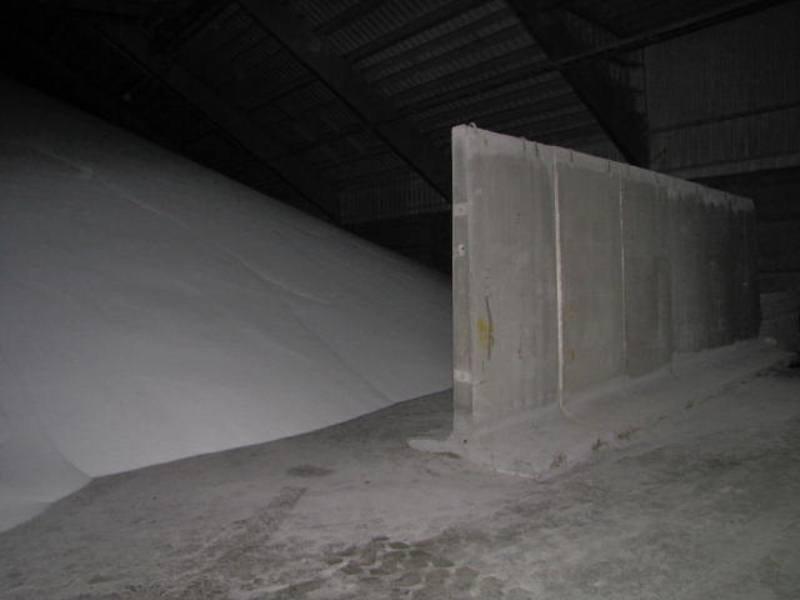
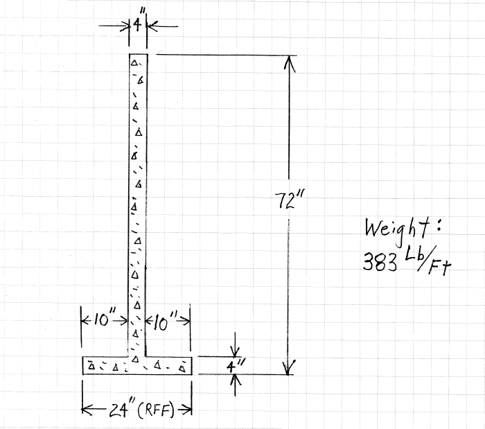
We have some concrete barriers at one of our warehouses that were purchased about 8-10 years ago. The concrete barriers are movable and are used to separate the different granular materials in the warehouse. How would one go about doing a calculation to determine whether these barriers are strong enough to hold back a pile of this granular material. The barriers are an upside down T-shape and I know the properties of the granular material (angle of repose, density, etc.)
 
Replies continue below

Recommended for you

The barriers are probably what is called "New Jersey Barrier" and were originally designed as the parapet for highway bridges:

URL]


For a first order approximation, calculate the force exerted by the granular material as an "equivalent fluid pressure". Consider one foot of barrier length. See "US Steel Sheet Piling Design Extracts" on my website for general information on how to make this calc:
SlideRuleEra.net

To determine the force the barrier will resist consider the barrier to have vertical sides (not true, but a ok for a first order calc). Estimate or determine the barrier weight (per ft. of length) and coefficient of friction between the barrier and the (assumed level) floor. Calculate the force that friction can resist.

Compare the two numbers and see what you get. If the material piled higher than the top of barrier, there will be additional considerations.

[idea]
[r2d2]
 
Here is a picture of the walls in question. The material will be piled higher than the walls.
Walls_005_c4az7k.jpg
 
You clearly will have an overturning issue. Further, the heel and toe of the retaining wall are very short, making anchorage difficult.

Will they withstand the loading? Don't know. Not sure how they are reinforced.
 
Ok, the sixth page of the US Steel document I suggested addresses "Inclined Bank" material.

For the friction calculations, add the weight of the material directly above the barrier's "foot" to the weight of the barrier.

Edit: Ron is right, overturning has to be considered, too. Sliding still may be the limiting value... the calcs will tell.

[idea]
[r2d2]
 
check point loads from heavy equipment impact on the walls
 
My gut feeling is that these will not carry what you have as they exist. Well meaning workers may overload them and over they go.

I'd consider taking one or two and cutting into short segments to be used as bracing. A few bolts through the brace "T" and the vertical of the main unit. Do some calcs to find the spacing.
 
 http://files.engineering.com/getfile.aspx?folder=c2efca27-2c65-494a-98df-1f8625a52a4a&file=P1010377.jpg
as per attached doc :

1 - a structural wall should be like shown on file "wall Fig 1"
2 - theoretically the ratio between dimensions should be like shown on file "wall fig 2"
3 - hopefully your barriers are not like "wall canal" because the steel reinforcement is not structural but only for handling (they are used as lining of water canal/flume)

I am going to prepare a file excel for calculation as per "wall fig 1" (just few days)

PS : since I am Italian, what is the difference canal - flume ? Thanks
 
 http://files.engineering.com/getfile.aspx?folder=42894662-d985-476b-bf80-3c8674c35ee4&file=wall.zip
From the replies above and just a gut feel - I think you'll be lucky if this doesn't start to move or overturn when you start loading it.

My concern really is that you won't have sufficient factor of safety and hence whilst it might be shown to have enough friction to stop it moving, any changes, water at the base or perhaps a sudden extra surcharge ( some material being dropped on it), will cause it to suddenly shift and if anyone is on the far side you could get a lot of flow of material.

Hence if you do this I would recommend you add some extra supports attached to the floor and walls to prevent this.

Perhaps talk to these guys - they really seem to know how to do it. Note that their inner toe is much longer than yours. also they look thicker at the base than your and taper a bit more.
Not sure how or if they connect the concrete sections together.

Remember - More details = better answers
Also: If you get a response it's polite to respond to it.
 
OP said:
How would one go about doing a calculation to determine whether these (existing) barriers are strong enough to hold back a pile of this granular material?

Interesting whether failure would be from sliding or overturning... so I performed basic hand / semi-graphical calculations based on some modest assumptions about a (hypothetical) 6' tall barrier with a narrow (2' wide) base:

Wall_Failure_Analysis-Model_Wall_htqg31.png


My results indicate he barrier will fail by sliding at a depth of about 4.0 Feet with fill (assumed to be "Dry River Sand" with a unit weight of 106 Lb/Ft3 and Angle of Repose of 33.7 Degrees).

If the barrier is restrained from sliding, failure by overturning would occur at a depth of approximately 4.5 Feet:

Wall_Failure_Analysis-Results_qvbkfm.png


A summary of all the calcs is attached.

[idea]
[r2d2]
 
How much longer would the inner toe have to beto work with a Fos of 1.5 The pictures of the proper ones suggest at least 3ft for a 6 foot high barrier.

Remember - More details = better answers
Also: If you get a response it's polite to respond to it.
 
with just a 4 inch thick footing and stem, you might also have structural failure of the wall due to the moment at the base if it is restrained from sliding / anchored down. you have only a single layer of vertical steel and making an assumption that the single layer of steel reinforcement is as scant as the concrete is, it is probably inadequate for the loading. For serviceability, I would have expected 10 - 12 inches thick concrete at a minimum
 
Thanks everyone. I was able to calculate the maximum height of product that would give a SF of 1.5 for both sliding and overturning. Here are the details of the real life example I have given:

I assumed Reinforced Concrete = 150 lb/ft3 as per the example above.
Total width of base = 5'
Base thickness = 6"
Height of barrier = 10' 2"
Barrier thickness = 8.5"

Material density = 57 lb/ft3
Angle of repose = 35 deg
Coefficient of Friction = 0.8 as per the example above

Using this information, I calculated that if the height of the product is 8.2 ft above the top of the base, the overturning SF is 2.12 and the Sliding SF is 1.50. (One thing I noticed in SlideRuleEra's example is you didn't include the small area of the inclined portion of the material in the weight calculation. Otherwise, it was great and easy to follow!)

The only unknown to me remaining is whether the barrier would structurally handle the load. The barrier is not anchored to the ground in anyway.

 
I think you guys are missing a couple of important factors. If the wall were to tilt it would pivot on the outside edge of the base. Also it would have to lift not only the granular material directly over the base but a wedge of material that starts at the inside edge of the base and angles away from the wall.
 
mas745 - Glad the example was helpful. I intentionally left out the weight of the inclined wedge of fill. Its' contribution to resisting both sliding and overturning is trivial. As I stated in my first post, the cals I'm presenting are a first order approximation... case in point: Assuming the Coefficient of Friction is 0.8 does NOT mean that it is 0.800. In fact, there are other credible references that say the COF should be between 0.60 and 0.75 (which reduces the sliding Safety Factor).

I checked your calcs and get somewhat lower Safety Factors for both sliding and overturning. You mentioned that "...the height of the product is 8.2 ft above the top of the base". If I'm reading this right, then the depth of the assumed Equivalent Fluid is 8.7 ft (8.2 ft + 0.5 ft base thickness). The product is "pushing" horizontally on the 6" high base every bit as much as the 8.2 ft. high wall. This may be the difference in our numbers.

Compositepro - I believe all the contributors are considering the "Tee" to be rigid and are summing moments about the outside toe.
The Rankine-Coulomb approach that I'm presenting considers the granular product to be a fluid... and to perform like one. To be consistent with other hydrostatic calcs, can't take advantage of any product weight that is not directly above the "Tee".

[idea]
[r2d2]
 
robyengIT - Sure. The OP shows a photo and says the product will be piled against the wall. For my hypothetical example I assumed that the Angle of Incline will equal the Angle of Repose. My one-page summaries of each calculation intentionally did not show every step. I wanted to see if any questions came up.

The sixth page of the US Steel document that I referenced in an early post shows how to calculate an "Equivalent Liquid Pressure" (ELP) for an inclined bank to make the calculations exactly the same as for a Level Bank (See fifth page of US Steel reference). On my summaries I noted, without explanation, that the ELP = 73.4 lb/ft2.

The ELP is then used for all of the following calculation: 330 lb @ 3' deep, 743 lb @ 4.5' deep, and 1320 lb @ 6' deep.

Here is the info from the sixth page (with my notes added) and fifth page:

Earth_Pressure_-_Inclined_Bank_kjuj48.png


Earth_Pressure_-_Level_Bank_zqo7dl.png


[idea]
[r2d2]
 
SlideRuleEra, I adjusted my calculations based on your comment that the product would be pushing on the base as well as the barrier wall. I now come up with a height of product 8.05 ft above the ground (7.55ft above the top of the base) for a safety factor of 1.5. Is this closer to the number you were getting?
 
Status
Not open for further replies.

Part and Inventory Search

Sponsor