Continue to Site

Eng-Tips is the largest engineering community on the Internet

Intelligent Work Forums for Engineering Professionals

  • Congratulations KootK on being selected by the Eng-Tips community for having the most helpful posts in the forums last week. Way to Go!

Concrete Beam Failure 2

Status
Not open for further replies.

Sweever

Structural
Sep 13, 2017
29
The attached photo is what I believe is a tension failure of a concrete beam. The beam is part of the foundation system for a large round steel storage bin. The beam is located within the outside ring wall where a conveyor/tunnel is located and penetrates the foundation wall. Thus necessitating an opening in the outside ring wall . Can anyone confirm that this looks like a tension failure? For some background, this particular bin foundation is composed a suspended one way concrete slab with intermediate concrete walls every 6 feet and a perimeter concrete ring wall around the circumference of the bin. All interior and perimeter concrete walls are supported on a large raft slab and piles. The perimeter ring beam acts as tension ring and carries vertical loads from the storage bin walls and part of the suspended slab.

I am guessing that maybe the contractor did not install of the correct number of tension tie reinforcement in the beam(contractor error). Any other ideas?

Any assistance is appreciated.
 
 http://files.engineering.com/getfile.aspx?folder=bc22636a-3c94-495c-8a0e-43634a667923&file=IMG_0534.JPG
Replies continue below

Recommended for you

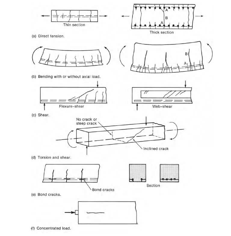
Just based on that photo, it looks like a flexural/shear failure, not a direct tension failure.
 
Meaning that the reinforcement within the beam was not anchored properly in the adjacent walls?
 
No, meaning that the beam was overloaded by vertical loading, causing failure in bending.
 
Flexural-shear

Capture_g40ruu.jpg
 
PaulG93,
shouldn't flexural cracks go all the way down until the bottom of the beam?
I don't think that this problem could be avoided if the beam had more tension reinforcement parallel with lower edge, it would only (maybe) reduce the cracks.

 
An update to this original question. We have received some more photos from the site and the cracking is not exactly what we originally thought. I have attached two additional photos, one overall view of beam in elevation and a second showing the underside of the beam. As you can see from the photo on the underside, only the front face of the beam has cracked and displaced downward. It is our theory that the concrete cover at the front face of the beam is excessive, maybe 3-4" and only the front face of the beam has sheared off at the interface of the beam stirrups. Thoughts?
 
 http://files.engineering.com/getfile.aspx?folder=f20395cd-9c9a-4776-852d-a87237367954&file=7.jpg
The contractor leaving out some re-bar is a good theory. Maybe a long shot here but: I would investigate those cable/angle supports. They appear to be attached with post-installed anchors. I've had quite a few contractors cut re-bar in placing those before.
 
It looks to me like the shear stirrups were left out. If there were shear stirrups, I think they would have confined the crack width? Likewise if there were shear stirrups (in a "U" configuration) they would have confined the width of the crack in the bottom of the beam. Is there anything else about this beam one would need to know to assess the cause of the cracks? (Is it post-tensioned? Is it single span or multiple span, and if so, what are the span dimensions? What is the loading diagram for the beam?)
 
[blue] (Sweever) [/blue]

It is our theory that the concrete cover at the front face of the beam is excessive, maybe 3-4" and only the front face of the beam has sheared off at the interface of the beam stirrups. Thoughts?

I doubt excessive cover is the cause. For one thing, the cracks seem pretty wide. And secondly, I've looked at slabs/walls in the field (with high moments near their capacity), with re-bar in the center of them......and I've never seen cracking this wide from it. Granted this is a beam not a slab......but if that was the problem, wouldn't it look more like a spalling failue (i.e. with chunks coming off)?
 
Any chance the formwork fell apart while this thing was still somewhat plastic?

I like to debate structural engineering theory -- a lot. If I challenge you on something, know that I'm doing so because I respect your opinion enough to either change it or adopt it.
 
Its possible the shear stirrups were left out, but really doubtful. The design calls for 15M @4" on center and we verified that the steel within the beam at the other end of the bin was placed correctly. Seems unlikely they would miss them at the this end. We are heading out there on Monday to review in depth and chip some of the concrete to see if we can see the rebar. Recent measurements for the site seem to indicated that the beam is 22" wide when the design calls for a 18" wide beam. I really believe there is too much cover on the outside face with no steel to tie it in. There are vertical bin stiffeners imposing point loads at the outside edge of the beam which you can see in the elevation photo.
 
Sweever, did you ever find out what the issue was?
 
Could be a combination of a few things here, but some shear failure would be on the top of the list rather than tensile failure, although that photo taken from the bottom has me tossed.
 
Probably inadequate lap lengths in the flexural reinforcing.... flex bars move ->mobilizes cover as shown. Counter to that is that the beam hasn't collapsed completely soooo?

Alternatively, was there any leakage of the water or other liquid above? If bars corrodded then maybe the bars bloated and spalled off the chunk of concreted?

Just ideas. end of the day, some shoring and removal of the concrete to inspect is the way to go.
 
Never heard of "bloated" bars, but I get your picture.
 
Perhaps not enough cover in bottom bars, a fairly corrosive environment and time caused the bottom bars to spall ?
 
The torsional ties for this edge beam did not engage. Could imagine the right wall settled down with the left end of the beam being a continuous/cantilevered at the support.
 
Status
Not open for further replies.

Part and Inventory Search

Sponsor