Continue to Site

Eng-Tips is the largest engineering community on the Internet

Intelligent Work Forums for Engineering Professionals

  • Congratulations pierreick on being selected by the Eng-Tips community for having the most helpful posts in the forums last week. Way to Go!

Concrete Bearing - A2/A1 1

Status
Not open for further replies.

Celt83

Structural
Sep 4, 2007
2,070
When determining the A2/A1 ratio is A2 based on a projection of the area in compression or a projection of the entire base/embed plate?

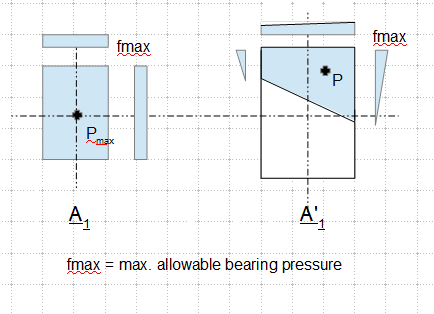
in attached image left is projection of base pl and right is projection of area in compression for a specific load set:
Capturebrg_uzbfk2.png


After reading the commentary in ACI 318-05,08,11 my interpretation is that A2/A1 should be based on the area in compression so the right setup in the above image.

My Personal Open Source Structural Applications:

Open Source Structural GitHub Group:
 
Replies continue below

Recommended for you

Will it change anything in the design? One could also assume a rectangle compressive block, or couldn't it be?
 
I feel fairly strongly that it should be based on the area in compression. No other interpretation would square with my understanding of the confinement effect that the provision purports to capture. I imagine that you're building this rather advanced checking capability into your own baseplate anchorage spreadsheet?
 
We have to think when is the check on A2/A1 is required in the design process, then see if it is necessary to make the change, even though the fact says it is correct.
 
KootK:
That is my understanding and oh I have plans..grand plans..but no time.

R13:
This has applications for any base plate or embed with one or more nearby edges, where if using the entire plate area A2/A1 may be limited to less than 4 resulting in a smaller allowable bearing stress. The smaller allowable bearing stress then potentially leads to a smaller design moment for the base plate/embed because the bearing depth increases reducing the moment arm.

My Personal Open Source Structural Applications:

Open Source Structural GitHub Group:
 
Below is a review on AISC column base support design procedures (strength factors are omitted for simplicity).

The "allowable bearing stress/strength" is the limit concrete stress/strength (depending on the ratio A1 and A2), specified by the codes, per AISC:

When the load acting/bear on the full concrete base area A1, fmax = 0.85fc', and
when the concrete base area is larger than the direct load contact area, A2 > A1, fmax= 0.85fc'[√A2/A1] ≤ 1.7fc', in which √A2/A1 ≤ 2.
Then, the required support area is derived by the general form A1 = Pmax/fmax for concentrically loaded column.

At this point, let A1 = Base Plate Area = B(width) x N(length), and qmax = fmax x B. For eccentrically loaded column, we must assure that e = M/P ≤ ecri = N/2 - P/(2qmax). If e > ecri, the base plate needs to be enlarged to ensure the resulting stress falls below, or equal to, the limiting stress qmax, or fmax. This may require a few iterations for complicate cases.

Once the base plate size is determined, the maximum allowable stress (0.85fc'), with appropriate adjustment factors, can then be used to design the steel base plate. I don't see shortcoming of this approach that requires change, or maybe I've missed something.

 
Not at all a criteria, this would lead to very uneconomical base plates, when e>e,crit you switch to the "Large" moment procedure

Pitfalls of the Design Guide 1 method:
1. strain compatibility is ignored, can lead to unconservative anchor tensions
2. various load conditions and plate configuration have no solution when setting q = f,max


My Personal Open Source Structural Applications:

Open Source Structural GitHub Group:
 
Sorry, I don't see your point. Maybe an example is helpful.

IMO, the A2 to A1 ratio is only used in the logic step to derive the least/minimum bearing area required for the anticipated largest compressive load. From that point on, the bearing area can only be enlarged for effect raised from the eccentric loadings by iterations, to ensure the concrete allowable bearing stress is not exceeded. There could have loop holes (maybe due to my ignorance, I've not notice one), but this is a long standing general approach specified by both AISC and ACI (with slight difference), I doubt the claim that it is unsafe. Do you have reference to support this claim?
 
The method was developed for rectangular plates and uni-axial moments, once you go outside those parameters the method begins to break down.

See Blodgett's approach in his book Design of Welded Structures which includes a form of strain compatibility, this method can be expanded to cover use cases of irregular plates and moments in two directions.

My Personal Open Source Structural Applications:

Open Source Structural GitHub Group:
 
I might go for that later. But for now, no matter what method you use to design the steel anchorage, the allowable concrete stress remains constant (0.85fc'), and this would be the maximum pressure you are allowed to impose on the base plate, agreed? In contrast, A1, and A2/A1 ratio are geometric parameters/variables to be defined in the initial step, by the applied load and the bearing pressure limit. Once beyond the initial step, the determination of final geometry of the bearing area, A1, is another ball game (could based on linear stress-strain, or non-linear, or...), but with the bearing pressure limit still remains the same. I think your focus is on the balance/method of the anchorage design, rather than the bearing pressure though.
 
A2 is the loaded area in compression.

I tend to side with @r13's approach. If your plate gets less and less evenly loaded (as per the OG sketch), the 0.85f'c would be more valid for finding a solution.
 
I don't see the reason for the query. If the BP on the right were trapezoidal in shape, then the increase in bearing would be permissable based on the areas, with the trapezoidal area fully loaded... with the intended loading the the loading of the trapezoidal area would be triangular based on the NA. This loading is less severe than being fully loaded. Easy answer...

Rather than think climate change and the corona virus as science, think of it as the wrath of God. Feel any better?

-Dik
 
Dik:
Didn't even think to look at it that way to much time down in the weeds. Thanks.

Steveh49:
Yep lets say an anchor in each corner of the plate with three of them in tension so that neutral axis is just shy of the corner anchors.

Skeletron:
A1 is defined as the area in compression
A2 is defined as a geometrically similar projection of A1 towards the concrete boundary at 45 degrees from the concrete surface.

My Personal Open Source Structural Applications:

Open Source Structural GitHub Group:
 
I reckon this situation is outside what the A2/A1 was originally based on. The tension anchors introduce tension stresses into the concrete: the stresses that cause splitting and cone failure. They probably disrupt the confinement to the bearing area, depending on geometry and load details. I can't say though whether the effect is significant.

Also, less severe loading is not always a given with concrete. Non-uniform compression is uniform compression (good for concrete) 'reduced' by a tension component (maybe not so good). Compression outside the kern is an obvious example.
 
Base plate design is usually done by iteration process. A1 and A2 are tools in the preliminary design to determine the least bearing/plate area (A1) required to support the maximum axial force. Upon introducing the eccentric loadings, a larger bearing/plate area (A1') maybe required to accommodate the end effects. Throughout the design process, the concrete allowable stress remains constant (0.85fc'), which in turn is the maximum compressive pressure can be applied to the base plate for anchorage design. The sketch below shows a design based on the elastic method.

image_ivkqqd.png

See revised sketch at post below.
 
Steveh49:
I went down a similar thought path. I think this kind of lands in a hole between the research on anchors and bearing. I'd wager that if the anchor failure cone overlapped the bearing area there may be a slight bump in breakout capacity with more of a bulb type strut developing between the anchor head and the compression area on one side and partial cone failure on the free side. For what its worth ACI I think 355.3, will correct this reference tomorrow, has worked examples for anchor design and they include the A2/A1 bump when working out the forces, as does AISC Design Guide 1.


R13:
If A2/A1 is applicable the design stress for the plate is not 0.85f'c but depending on the ratio can be up to 2*0.85f'c=1.7f'c which you indicated a few posts ago but now seem to be walking back on. My interpretation is the ratio is not simply a preliminary check but an integral part of the design iterations.

My Personal Open Source Structural Applications:

Open Source Structural GitHub Group:
 
I think the Australian Standard (based on Euro I think) for anchors gives increase in cone capacity for compression over part of the cone, but I don't recall this compression bearing check being covered. The same hole you mentioned.
 
You are correct that the sketch is somewhat misleading by calling out 0.85fc' as the allowable bearing pressure. So let's correct it to fmax, to represent whatever the maximum allowable bearing stress based on the rules set previously.

image_ogfbt0.png
 
Some things... for bearing plates, I never consider the increase in bearing due to areas... I always use a rectangular stress block for concrete, never triangular and I never use grout strength rather than concrete strength... I think it's conservative, but like column design... I don't really want a tight design.

Rather than think climate change and the corona virus as science, think of it as the wrath of God. Feel any better?

-Dik
 
Status
Not open for further replies.

Part and Inventory Search

Sponsor